DM385, DM388
www.ti.com
SPRS821D –MARCH 2013–REVISED DECEMBER 2013
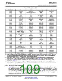
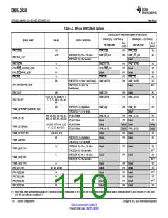
Table 4-1. Boot Mode Order
BTMODE[4:0]
1st
RESERVED
UART
2nd
RESERVED
XIP w/WAIT (MUX0)(1)(2)
SPI
3rd
RESERVED
MMC
4th
RESERVED
SPI
00000
00001
00010
00011
00100
00101
00110
00111
01000
01001
01010
01011
01100
01101
01110
01111
10000
10001
10010
10011
10100
10101
10110
10111
11000
11001
11010
11011
11100
11101
11110
11111
UART
NAND
XIP (MUX0)(1)(2)
NANDI2C
MMC
UART
EMAC(3)
SPI
SPI
NAND
NANDI2C
RESERVED
RESERVED
XIP (MUX1)(1)(2)
RESERVED
RESERVED
RESERVED
RESERVED
RESERVED
RESERVED
RESERVED
PCIE_64(4)
MMC
RESERVED
RESERVED
EMAC(3)
RESERVED
RESERVED
MMC
RESERVED
RESERVED
SPI
PCIE_32(4)
PCIE_64(4)
RESERVED
RESERVED
RESERVED
RESERVED
RESERVED
Fast XIP (MUX0)(1)
XIP (MUX1)(1)(2)
RESERVED
RESERVED
RESERVED
RESERVED
RESERVED
RESERVED
RESERVED
UART
RESERVED
RESERVED
RESERVED
RESERVED
RESERVED
RESERVED
RESERVED
EMAC(3)
EMAC(3)
EMAC(3)
SPI
UART
XIP w/WAIT (MUX1)(1)(2)
UART
NANDI2C
NANDI2C
NANDI2C
MMC
MMC
NAND
UART
NAND
MMC
UART
EMAC(3)
NAND
SPI
EMAC(3)
NANDI2C
UART
EMAC(3)
EMAC(3)
SPI
MMC
UART
MMC
SPI
UART
SPI
MMC
PCIE_32(4)
PCIE_64(4)
SPI
RESERVED
RESERVED
MMC
SPI
MMC
XIP (MUX0)(1)(2)
XIP w/WAIT (MUX0)(1)(2)
RESERVED
RESERVED
RESERVED
Fast XIP (MUX0)(1)
UART
UART
SPI
MMC
RESERVED
RESERVED
RESERVED
EMAC(3)
RESERVED
RESERVED
RESERVED
UART
RESERVED
RESERVED
RESERVED
PCIE_32(4)
(1) GPMC CS0 eXecute In Place (XIP) boot for NOR/OneNAND/ROM. MUX0/1 refers to the multiplexing option for the GPMC_A[12:0] pins.
For more detailed information on booting the device, including which pins are used for each boot mode, see the ROM Code Memory
and Peripheral Booting chapter in the device-specific Technical Reference Manual.
(2) When the XIP (MUX0), XIP (MUX1), XIP w/ WAiT (MUX0) or XIP w/ WAiT (MUX1) bootmode is selected, the sampled value from
BTMODE[10] pin is used to select between GPMC pin configuration options shown in Table 4-2, XIP (on GPMC) Boot Options.
(3) When the EMAC bootmode is selected, the sampled value from BTMODE[9:8] pins are used to determine the Ethernet PHY Mode
Selection (see Table 4-7).
(4) When the PCIe bootmode is selected (PCIE_32 or PCI_64), the sampled value from BTMODE[15:12] pins are used to determine the
addressing options. For more detailed information on the PCIe addressing options, see the ROM Code Memory and Peripheral Booting
chapter in the device-specific Technical Reference Manual.
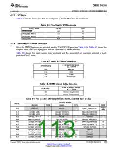
4.2.1 XIP (NOR) Boot Options
Table 4-2 shows the XIP (NOR) boot mode GPMC pin configuration options (Option A: BTMODE[10] = 0
and Option B: BTMODE[10] = 1). For Option B, the pull state on select pins is reconfigured to IPD and
remains IPD after boot until the user software reconfigures it. In Table 4-2, GPMC_A[1:12] are configured
only for Non-Muxed NOR flash. In the case of Muxed NOR Flash, GPMC_D[15:0] act as both address and
data lines so configuration of GPMC_A[1:12] in XIP_Mux0 mode and XIP_Mux1 mode doesn't apply for a
Muxed NOR flash and those pins are not configured by Boot ROM.
Copyright © 2013, Texas Instruments Incorporated
Device Configurations
109
Submit Documentation Feedback
Product Folder Links: DM385 DM388

 TI [ TEXAS INSTRUMENTS ]