DM385, DM388
SPRS821D –MARCH 2013–REVISED DECEMBER 2013
www.ti.com
4 Device Configurations
4.1 Control Module Registers
4.2 Boot Modes
The state of the device after boot is determined by sampling the input states of the BTMODE[15:0] pins
when device reset (POR or RESET) is de-asserted. The sampled values are latched into the
CONTROL_STATUS register, which is part of the Control Module. The BTMODE[15:11] values determine
the following system boot settings:
•
•
RSTOUT_WD_OUT Control
GPMC CS0 Default Data Bus Width, Wait Enable, and Address/Data Multiplexing
For additional details on BTMODE[15:11] pin functions, see Table 3-13, Boot Configuration Terminal
Functions.
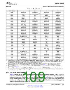
The BTMODE[4:0] values determine the boot mode order according to Table 4-1, Boot Mode Order. The
1st boot mode listed for each BTMODE[4:0] configuration is executed as the primary boot mode. If the
primary boot mode fails, the 2nd, 3rd, and 4th boot modes are executed in that order until a successful
boot is completed.
The BTMODE[6:5] pins are RESERVED and should be pulled down as indicated in Table 3-13, Boot
Configuration Terminal Functions.
When the EMAC bootmode is selected (see Table 4-1), the sampled value from BTMODE[9:8] pins are
used to determine the Ethernet PHY Mode selection (see Table 4-7) and the BTMODE[7] pin is used for
RGMII Internal Delay selection (see Table 4-8).
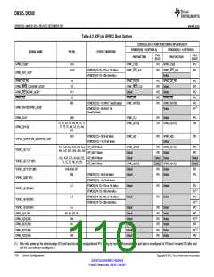
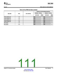
When the XIP (MUX0), XIP (MUX1), XIP w/ WAiT (MUX0) or XIP w/ WAiT (MUX1) bootmode is selected
(see Table 4-1), the sampled value from BTMODE[10] pin is used to select between GPMC pin muxing
options shown in Table 4-2, XIP (on GPMC) Boot Options [Muxed or Non-Muxed].
For more detailed information on booting the device, including which pins are used for each boot mode,
see the ROM Code Memory and Peripheral Booting chapter in the device-specific Technical Reference
Manual.
108
Device Configurations
Copyright © 2013, Texas Instruments Incorporated
Submit Documentation Feedback
Product Folder Links: DM385 DM388

 TI [ TEXAS INSTRUMENTS ]