DM385, DM388
SPRS821D –MARCH 2013–REVISED DECEMBER 2013
www.ti.com
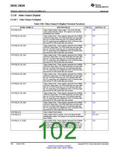
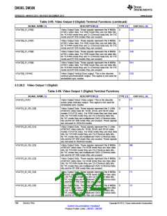
Table 3-55. Video Output 0 (Digital) Terminal Functions (continued)
SIGNAL NAME [1]
VOUT[0]_R_CR[6]
DESCRIPTION [2]
TYPE [3]
AAR BALL [4]
C30
Video Output Data. These signals represent the 8 MSBs
of R/Cr video data. For RGB mode they are red data bits,
for YUV444 mode they are Cr (Chroma) data bits, for Y/C
mode and BT.656 modes they are unused.
O
VOUT[0]_R_CR[7]
VOUT[0]_R_CR[8]
VOUT[0]_R_CR[9]
VOUT[0]_VSYNC
Video Output Data. These signals represent the 8 MSBs
of R/Cr video data. For RGB mode they are red data bits,
for YUV444 mode they are Cr (Chroma) data bits, for Y/C
mode and BT.656 modes they are unused.
O
O
O
O
B30
A30
B31
E20
Video Output Data. These signals represent the 8 MSBs
of R/Cr video data. For RGB mode they are red data bits,
for YUV444 mode they are Cr (Chroma) data bits, for Y/C
mode and BT.656 modes they are unused.
Video Output Data. These signals represent the 8 MSBs
of R/Cr video data. For RGB mode they are red data bits,
for YUV444 mode they are Cr (Chroma) data bits, for Y/C
mode and BT.656 modes they are unused.
Video Output Vertical Sync output. This is the discrete
vertical synchronization output. This signal is not used for
embedded sync modes.
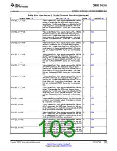
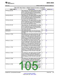
3.3.26.2 Video Output 1 (Digital)
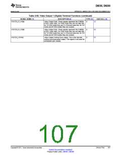
Table 3-56. Video Output 1 (Digital) Terminal Functions
SIGNAL NAME [1]
VOUT[1]_AVID
DESCRIPTION [2]
TYPE [3]
AAR BALL [4]
Video Output Active Video output. This is the discrete
active video indicator output. This signal is not used for
embedded sync modes.
O
F1
H9
VOUT[1]_B_CB_C[0]
Video Output Data. These signals represent the 2 LSBs
of B/Cb/C video data for 10-bit, 20-bit, and 30-bit video
modes (VOUT[1] only). For RGB mode they are blue data
bits, for YUV444 mode they are Cb (Chroma) data bits,
for Y/C mode they are multiplexed Cb/Cr (Chroma) data
bits and for BT.656 mode they are unused. These signals
are not used in 16/24-bit modes.
O
VOUT[1]_B_CB_C[1]
Video Output Data. These signals represent the 2 LSBs
of B/Cb/C video data for 10-bit, 20-bit, and 30-bit video
modes (VOUT[1] only). For RGB mode they are blue data
bits, for YUV444 mode they are Cb (Chroma) data bits,
for Y/C mode they are multiplexed Cb/Cr (Chroma) data
bits and for BT.656 mode they are unused. These signals
are not used in 16/24-bit modes.
O
D5
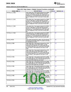
VOUT[1]_B_CB_C[2]
VOUT[1]_B_CB_C[3]
VOUT[1]_B_CB_C[4]
VOUT[1]_B_CB_C[5]
Video Output Data. These signals represent the 8 MSBs
of B/Cb/C video data. For RGB mode they are blue data
bits, for YUV444 mode they are Cb (Chroma) data bits,
for Y/C mode they are multiplexed Cb/Cr (Chroma) data
bits and for BT.656 mode they are unused.
O
O
O
O
M8
F2
F3
G1
Video Output Data. These signals represent the 8 MSBs
of B/Cb/C video data. For RGB mode they are blue data
bits, for YUV444 mode they are Cb (Chroma) data bits,
for Y/C mode they are multiplexed Cb/Cr (Chroma) data
bits and for BT.656 mode they are unused.
Video Output Data. These signals represent the 8 MSBs
of B/Cb/C video data. For RGB mode they are blue data
bits, for YUV444 mode they are Cb (Chroma) data bits,
for Y/C mode they are multiplexed Cb/Cr (Chroma) data
bits and for BT.656 mode they are unused.
Video Output Data. These signals represent the 8 MSBs
of B/Cb/C video data. For RGB mode they are blue data
bits, for YUV444 mode they are Cb (Chroma) data bits,
for Y/C mode they are multiplexed Cb/Cr (Chroma) data
bits and for BT.656 mode they are unused.
104
Device Pins
Copyright © 2013, Texas Instruments Incorporated
Submit Documentation Feedback
Product Folder Links: DM385 DM388

 TI [ TEXAS INSTRUMENTS ]