DM385, DM388
SPRS821D –MARCH 2013–REVISED DECEMBER 2013
3.3.26 Video Output (Digital)
3.3.26.1 Video Output 0 (Digital)
www.ti.com
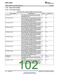
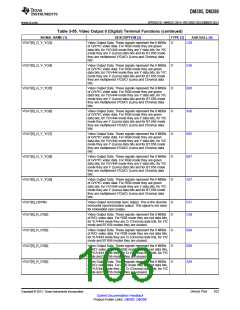
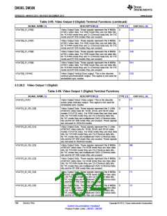
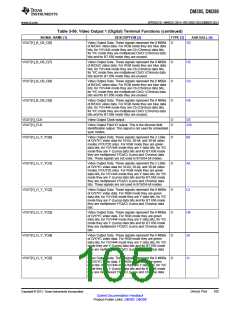
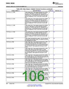
Table 3-55. Video Output 0 (Digital) Terminal Functions
SIGNAL NAME [1]
VOUT[0]_AVID
DESCRIPTION [2]
TYPE [3]
AAR BALL [4]
C20
Video Output Active Video output. This is the discrete
active video indicator output. This signal is not used for
embedded sync modes.
O
VOUT[0]_B_CB_C[2]
VOUT[0]_B_CB_C[3]
VOUT[0]_B_CB_C[4]
VOUT[0]_B_CB_C[5]
VOUT[0]_B_CB_C[6]
VOUT[0]_B_CB_C[7]
VOUT[0]_B_CB_C[8]
VOUT[0]_B_CB_C[9]
Video Output Data. These signals represent the 8 MSBs
of B/Cb/C video data. For RGB mode they are blue data
bits, for YUV444 mode they are Cb (Chroma) data bits,
for Y/C mode they are multiplexed Cb/Cr (Chroma) data
bits and for BT.656 mode they are unused.
O
O
O
O
O
O
O
O
F24
D21
J23
H23
J24
E24
D24
C24
Video Output Data. These signals represent the 8 MSBs
of B/Cb/C video data. For RGB mode they are blue data
bits, for YUV444 mode they are Cb (Chroma) data bits,
for Y/C mode they are multiplexed Cb/Cr (Chroma) data
bits and for BT.656 mode they are unused.
Video Output Data. These signals represent the 8 MSBs
of B/Cb/C video data. For RGB mode they are blue data
bits, for YUV444 mode they are Cb (Chroma) data bits,
for Y/C mode they are multiplexed Cb/Cr (Chroma) data
bits and for BT.656 mode they are unused.
Video Output Data. These signals represent the 8 MSBs
of B/Cb/C video data. For RGB mode they are blue data
bits, for YUV444 mode they are Cb (Chroma) data bits,
for Y/C mode they are multiplexed Cb/Cr (Chroma) data
bits and for BT.656 mode they are unused.
Video Output Data. These signals represent the 8 MSBs
of B/Cb/C video data. For RGB mode they are blue data
bits, for YUV444 mode they are Cb (Chroma) data bits,
for Y/C mode they are multiplexed Cb/Cr (Chroma) data
bits and for BT.656 mode they are unused.
Video Output Data. These signals represent the 8 MSBs
of B/Cb/C video data. For RGB mode they are blue data
bits, for YUV444 mode they are Cb (Chroma) data bits,
for Y/C mode they are multiplexed Cb/Cr (Chroma) data
bits and for BT.656 mode they are unused.
Video Output Data. These signals represent the 8 MSBs
of B/Cb/C video data. For RGB mode they are blue data
bits, for YUV444 mode they are Cb (Chroma) data bits,
for Y/C mode they are multiplexed Cb/Cr (Chroma) data
bits and for BT.656 mode they are unused.
Video Output Data. These signals represent the 8 MSBs
of B/Cb/C video data. For RGB mode they are blue data
bits, for YUV444 mode they are Cb (Chroma) data bits,
for Y/C mode they are multiplexed Cb/Cr (Chroma) data
bits and for BT.656 mode they are unused.
VOUT[0]_CLK
VOUT[0]_FLD
Video Output Clock output
O
O
K22
Video Output Field ID output. This is the discrete field
identification output. This signal is not used for embedded
sync modes.
B3, C20
VOUT[0]_G_Y_YC[2]
Video Output Data. These signals represent the 8 MSBs
of G/Y/YC video data. For RGB mode they are green
data bits, for YUV444 mode they are Y data bits, for Y/C
mode they are Y (Luma) data bits and for BT.656 mode
they are multiplexed Y/Cb/Cr (Luma and Chroma) data
bits.
O
C25
102
Device Pins
Copyright © 2013, Texas Instruments Incorporated
Submit Documentation Feedback
Product Folder Links: DM385 DM388

 TI [ TEXAS INSTRUMENTS ]