CC2510Fx / CC2511Fx
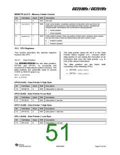
ACC (0xE0) - Accumulator
Bit
Field Name
Reset
R/W
Description
7:0
ACC[7:0]
0x00
R/W
Accumulator
10.3.5 B Register
purposes it may be used as a scratch-pad
register to hold temporary data.
The B register is used as the second 8-bit
argument during execution of multiply and
divide instructions. When not used for these
B (0xF0) - B Register
Bit
Field Name
Reset
R/W
Description
B register. Used in MUL and DIV instructions.
7:0
B[7:0]
0x00
R/W
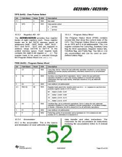
10.3.6 Stack Pointer
is incremented once to start from location
0x08, which is the first register (R0) of the
second register bank. Thus, in order to use
more than one register bank, the SPshould be
initialized to a different location not used for
data storage.
The stack resides in DATA memory space and
grows upwards. The PUSH instruction first
increments the Stack Pointer (SP) and then
copies the byte into the stack. The Stack
Pointer is initialized to 0x07 after a reset and it
SP (0x81) - Stack Pointer
Bit
Field Name
Reset
R/W
Description
7:0
SP[7:0]
0x07
R/W
Stack Pointer
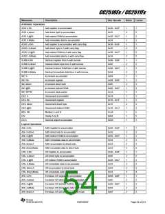
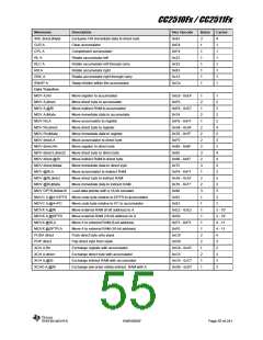
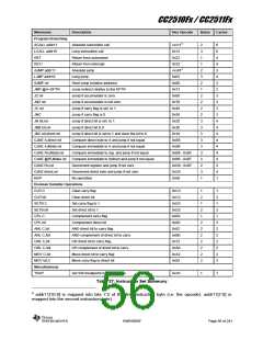
10.4 Instruction Set Summary
The 8051 instruction set is summarized in
Table 37. All mnemonics copyrighted © Intel
Corporation 1980.
• addr16 - 16-bit destination address.
Used by LCALL and LJMP. A branch
can be anywhere within the 8/16/32 KB
CODE memory space.
The following conventions are used in the
instruction set summary:
• addr11 - 11-bit destination address.
Used by ACALL and AJMP. The branch
will be within the same 2 KB page of
program memory as the first byte of the
following instruction.
• Rn - Register R7 - R0 of the currently
selected register bank.
• direct - 8-bit internal data location’s
address. This can be DATA area (0x00 -
0x7F) or SFR area (0x80 - 0xFF).
• rel - Signed (two’s complement) 8-bit
offset byte. Used by SJMP and all
conditional jumps. Range is –128 to
+127 bytes relative to first byte of the
following instruction.
• @Ri - 8-bit internal data location, DATA
area (0x00 - 0xFF) addressed indirectly
through register R1or R0.
• bit - direct addressed bit in DATA area
• #data - 8-bit constant included in
or SFR.
instruction.
The instructions that affect CPU flag settings
located in PSW are listed in Table 38 on Page
57. Note that operations on the PSWregister or
bits in PSWwill also affect the flag settings.
• #data16 - 16-bit constant included in
instruction.
SWRS055F
Page 53 of 241

 TI [ TEXAS INSTRUMENTS ]