CC2510Fx / CC2511Fx
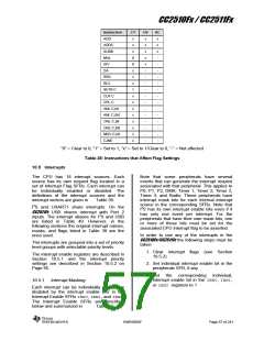
Instruction
ADD
CY
x
OV
x
x
x
x
x
-
AC
x
x
x
-
-
-
-
-
-
-
-
-
-
-
-
-
-
ADDC
x
SUBB
x
MUL
0
0
x
DIV
DA
RRC
x
-
RLC
x
-
SETB C
CLR C
CPL C
ANL C,bit
ANL C,/bit
ORL C,bit
ORL C,/bit
MOV C,bit
CJNE
1
x
-
-
x
-
x
-
x
-
x
-
x
-
x
-
x
-
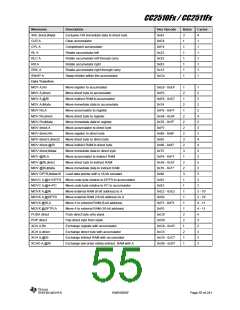
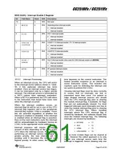
“0” = Clear to 0, “1” = Set to 1, “x” = Set to 1/Clear to 0, “-“ = Not affected
Table 38: Instructions that Affect Flag Settings
10.5 Interrupts
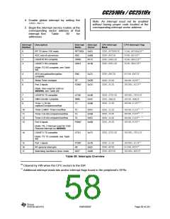
The CPU has 18 interrupt sources. Each
source has its own request flag located in a
set of Interrupt Flag SFRs. Each interrupt can
be individually enabled or disabled. The
definitions of the interrupt sources and the
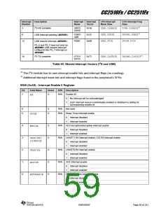
Note that some peripherals have several
events that can generate the interrupt request
associated with that peripheral. This applies to
P0, P1, P2, DMA, Timer 1, Timer 2, Timer 3,
Timer 4, and Radio. These peripherals have
interrupt mask bits for each internal interrupt
source in the corresponding SFRs. Note that
I2S has its own interrupt enable bits even if it
has only one event per interrupt. For the
peripherals that have their own mask bits, one
or more of these bits must be set for the
associated CPU interrupt flag to be asserted.
interrupt vectors are given in
Table 39.
I2S and USART1 share interrupts. On the
CC2511Fx USB shares interrupt with Port 2
inputs. The interrupt aliases for I2S and USB
are listed in Table 40. However, in the
following sections the original interrupt names,
masks, and flags listed in Table 39 are the
ones used.
In order to use any of the interrupts in the
CC2510Fx/CC2511Fx the following steps must be
taken:
The interrupts are grouped into a set of priority
level groups with selectable priority levels.
1. Clear interrupt flags (see Section
10.5.2)
The interrupt enable registers are described in
Section 10.5.1 and the interrupt priority
settings are described in Section 10.5.2 on
Page 65.
2. Set individual interrupt enable bit in the
peripherals SFR, if any
3. Set the corresponding individual,
interrupt enable bit in the IEN0, IEN1,
or IEN2 registers to 1
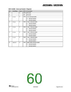
10.5.1 Interrupt Masking
Each interrupt can be individually enabled or
disabled by the interrupt enable bits in the
Interrupt Enable SFRs IEN0, IEN1, and IEN2.
The Interrupt Enable SFRs are described
below and summarized in
Table 39.
SWRS055F
Page 57 of 241

 TI [ TEXAS INSTRUMENTS ]