CC1110Fx / CC1111Fx
on P1 it is the user’s responsibility to make
sure that there is a conclusive order of
precedence based on the PERCFGand P2SEL
settings.
responsibility to avoid configurations where the
order of precedence is not conclusive.
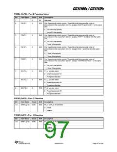
12.4.6.3 Timer 1
PERCFG.T1CFG selects whether to use
alternative 1 or alternative 2 locations.
12.4.6.2 USART1
The SFR bit PERCFG.U1CFG selects whether
to use alternative 1 or alternative 2 locations.
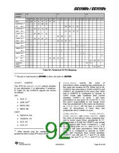
In Table 50, the USART1 signals are shown
as follows:
In Table 50, the Timer 1 signals are shown as
follows:
Channel 0 capture/compare pin: 0
Channel 1 capture/compare pin: 1
Channel 2 capture/compare pin: 2
SPI:
SCK: C
SSN: SS16
MOSI: MO
MISO: MI
UART:
P2DIR.PRIP0
selects
the
order
of
precedence when assigning two peripherals to
the same pin location on P0. When set to 10
or 11, Timer 1 has precedence over USART1
and USART0 respectively. It is the user’s
responsibility to not assign more than two
peripherals to the same pin locations
RXDATA: RX
TXDATA: TX
RTS: RT
CTS: CT
P2SEL.PRI3P1,
P2SEL.PRI2P1,
P2SEL.PRI1P1, and P2SEL.PRI0P1 select
the order of precedence when assigning two,
and in some cases three, peripherals to P1.
When
P2SEL.PRI1P1=0
and
P2DIR.PRIP0
selects
the
order
of
P2SEL.PRI0P1=1, Timer 1 has precedence
over Timer 4 and USART0 respectively. It is
the user’s responsibility to avoid configurations
where the order of precedence is not
conclusive.
precedence when assigning two peripherals to
the same pin location on P0. When set to 01,
USART1 has precedence if both USART0 and
USART1 are assigned to the same pins. Note
that if USART1 is configured to operate in
UART mode with hardware flow control
disabled, USART0 or timer 1 will have
precedence to use ports P0_3 and P0_2. It is
the user’s responsibility to not assign more
than two peripherals to the same pin locations,
as P2DIR.PRIP0 will not give a conclusive
order of precedence if more than two
peripherals are in conflict on a pin.
12.4.6.4 Timer 3
PERCFG.T3CFG selects whether to use
alternative 1 or alternative 2 locations.
In Table 50, the Timer 3 signals are shown as
follows:
Channel 0 compare pin: 0
Channel 1 compare pin: 1
P2SEL.PRI3P1,
P2SEL.PRI2P1,
P2SEL.PRI1P1, and P2SEL.PRI0P1 select
the order of precedence when assigning two,
and in some cases three, peripherals to P1. By
setting PRI3P1 to 1 and PRI2P1 to 0,
USART1 will have precedence over both
USART0 and Timer 3. However, if USART1 is
configured to operate in UART mode with
hardware flow control disabled, there will be a
conflict on P1_4 between USART0 and Timer
3 (channel 1), which the P2SEL register
settings do not solve. It is the user’s
P2SEL.PRI3P1,
P2SEL.PRI2P1,
P2SEL.PRI1P1, and P2SEL.PRI0P1 select
the order of precedence when assigning two,
and in some cases three, peripherals to P1.
Setting P2SEL.PRI2P1=1 gives Timer 3
precedence over USART1. It is the user’s
responsibility to avoid configurations where the
order of precedence is not conclusive.
12.4.6.5 Timer 4
16
PERCFG.T4CFG selects whether to use
alternative 1 or alternative 2 locations.
SSN should only be configured as a
peripheral when using SPI slave mode
In Table 50, the Timer 4 signals are shown as
follows:
SWRS033H
Page 93 of 246

 TI [ TEXAS INSTRUMENTS ]