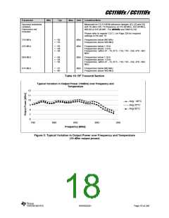
CC1110Fx / CC1111Fx
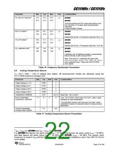
Parameter
Min
Typ
Max
Unit
Condition/Note
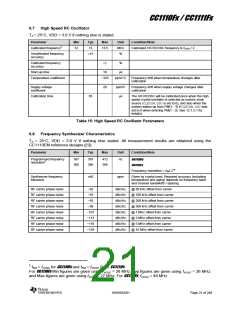
PLL turn-on / hop time4
72.4
81.4
75.2
81.4
75.2
81.4
s
CC1110Fx
CC1111Fx
Time from leaving the IDLE state until arriving in the
RX, FSTXON, or TX state, when not performing
calibration.
Crystal oscillator running.
RX to TX switch 4
TX to RX switch 4
PLL calibration time4
29.0
32.6
30.1
32.6
30.1
32.6
s
s
s
CC1110Fx
CC1111Fx
Settling time for the 1∙IF frequency step from RX to TX
30.0
33.6
31.1
33.6
31.1
33.6
CC1110Fx
CC1111Fx
Settling time for the 1∙IF frequency step from TX to RX
707
796
735
796
735
796
CC1110Fx
CC1111Fx
Calibration can be initiated manually or automatically
before entering or after leaving RX/TX.
Note: This is the PLL calibration time given that
TEST0=0x0Band FSCAL3.CHP_CURR_CAL_EN=10
(max calibration time). Please see DN110 [15] for
more details
Table 16: Frequency Synthesizer Parameters
6.9 Analog Temperature Sensor
TA= 25 C, VDD = 3.0V if nothing else stated. All measurement results are obtained using the
CC1110EM reference designs ([1]).
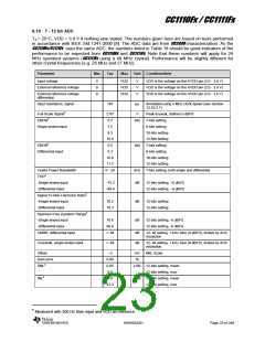
Parameter
Min
Typ
Max
Unit
Condition/Note
0.660
0.755
0.859
0.958
2.47
0
V
V
V
V
Output voltage at −0 C
Output voltage at 0 C
Output voltage at 40 C
Output voltage at 80 C
Temperature coefficient
mV/ C Fitted from −20 C to 80 C
Error in calculated
−2 *
2 *
C
From –20 C to 80 C when using 2.47 mV/ C, after 1-point
temperature, calibrated
calibration at room temperature
* The indicated minimum and maximum error with 1-point
calibration is based on measured values for typical process
parameters
Current consumption
0.3
mA
increase when enabled
Table 17: Analog Temperature Sensor Parameters
4 fRef = fXOSC for CC1110Fx and fRef = fXOSC /2 for CC1111Fx
For CC1110Fx Min figures are given using fXOSC = 27 MHz. Typ figures are given using fXOSC = 26 MHz,
and Max figures are given using fXOSC = 26 MHz. For CC1111Fx, fXOSC = 48 MHz The system clock
frequency is equal to fRef and the data rate is 250 kBaud. No PA ramping is used. See DN110 [15] for
more details.
SWRS033H
Page 22 of 246

 TI [ TEXAS INSTRUMENTS ]