CC1110Fx / CC1111Fx
timer. See Section 13.12.3 on Page 205 for
details.
The RSSI value is in dBm with ½ dB
resolution. The RSSI update rate, fRSSI
,
depends on the receiver filter bandwidth
(BWchannel defined in Section 13.6) and
AGCCTRL0.FILTER_LENGTH.
The preamble quality estimator increases an
internal counter by one each time a bit is
received that is different from the previous bit,
and decreases the counter by 8 each time a bit
is received that is the same as the last bit. The
threshold is configured with the register field
PKTCTRL1.PQT. A threshold of 4∙PQT for this
counter is used to gate sync word detection.
By setting the value to zero, the preamble
quality qualifier of the sync word is disabled.
2 BWchannel
8 2FILTER _ LENGTH
fRSSI
If PKTCTRL1.APPEND_STATUS is enabled the
RSSI value at sync word detection is
automatically added to the first byte appended
after the data payload.
A “Preamble Quality Reached” signal can be
observed on P1_5, P1_6, or P1_7 by setting
IOCFGx.GDOx_CFG=1000. It is also possible
to determine if preamble quality is reached by
checking the PQT_REACHED bit in the
PKTSTATUS register. This signal / bit asserts
when the received signal exceeds the PQT.
The RSSI value read from the RSSI status
register is a 2’s complement number. The
following procedure can be used to convert the
RSSI reading to an absolute power level
(RSSI_dBm).
1) Read the RSSI status register
2) Convert the reading from a hexadecimal
13.10.3 RSSI
number
to
a
decimal
number
The RSSI value is an estimate of the signal
level in the chosen channel. This value is
based on the current gain setting in the RX
chain and the measured signal level in the
channel.
(RSSI_dec)
3) If RSSI_dec ≥ 128 then RSSI_dBm =
(RSSI_dec – 256)/2 – RSSI_offset
4) Else if RSSI_dec < 128 then RSSI_dBm
= (RSSI_dec)/2 – RSSI_offset
In RX mode, the RSSI value can be read
continuously from the RSSI status register until
the demodulator detects a sync word (when
sync word detection is enabled). At that point
the RSSI readout value is frozen until the next
time the chip enters the RX state.
Table 68 provides typical values for the
RSSI_offset.
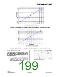
Figure 52 and Figure 53 shows typical plots of
RSSI readings as a function of input power
level for different data rates.
Note: It takes some time from the radio
enters RX mode until a valid RSSI value is
present in the RSSI register. Please see
DN505 [16] for details on how the RSSI
response time can be estimated.
Data rate [kBaud]
RSSI_offset [dB], 315 MHz
RSSI_offset [dB], 433 MHz
RSSI_offset [dB], 868 MHz
1.2
38.4
250
74
73
74
75
74
73
73
73
77
Table 68: Typical RSSI_offset Values
Figure 52 and Figure 53 show typical plots of
RSSI readings as a function of input power
level for different data rates.
SWRS033H
Page 198 of 246

 TI [ TEXAS INSTRUMENTS ]