CC1110Fx / CC1111Fx
If FEC/Interleaving is enabled, everything
following the sync words will be scrambled by
the interleaver and FEC encoded before being
modulated. FEC is enabled by setting
MDMCFG1.FEC_EN=1.
handler stores this value as the packet length
and receives the number of bytes indicated by
the length byte. If fixed packet length mode is
used, the packet handler will accept the
programmed number of bytes.
Next, the packet handler optionally checks the
address and only continues the reception if the
address matches. If automatic CRC check is
enabled, the packet handler computes CRC
and matches it with the appended CRC
checksum.
13.8.5
Packet Handling in Receive Mode
In receive mode, the demodulator and packet
handler will search for a valid preamble and
the sync word. When found, the demodulator
has obtained both bit and byte synchronism
and will receive the first payload byte.
At the end of the payload, the packet handler
will optionally write two extra packet status
bytes that contain CRC status, link quality
indication and RSSI value.
If FEC/Interleaving is enabled, the FEC
decoder will start to decode the first payload
byte. The interleaver will de-scramble the bits
before any other processing is done to the
data.
If a byte is received in the RFD register, and it
is not read before the next byte is received, the
radio will enter RX_OVERFLOW state and the
RFIF.IRQ_RXOVF flag will be set together
with RFIF.IRQ_DONE. An SIDLE strobe needs
to be issued to return to IDLE state.
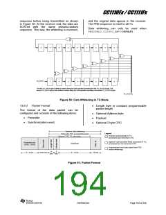
If whitening is enabled, the data will be de-
whitened at this stage.
When variable packet length mode is enabled,
the first byte is the length byte. The packet
13.9 Modulation Formats
When FSK/GFSK modulation is used the
DEVIATN register specifies the expected
frequency deviation of incoming signal in RX
and should be the same as the TX deviation
for demodulation to be performed reliably and
robustly.
CC1110Fx/CC1111Fx supports frequency and
phase shift modulation formats. The desired
modulation
format
is
set
in
the
MDMCFG2.MOD_FORMAT register.
Optionally, the data stream can be Manchester
coded by the modulator and decoded by the
demodulator. This option is enabled by setting
MDMCFG2.MANCHESTER_EN=1.
The frequency deviation is programmed with
the DEVIATION_M and DEVIATION_E values
in the DEVIATN register. The value has an
exponent/mantissa form, and the resultant
deviation is given by:
Note: Manchester encoding is not
supported at the same time as using the
FEC/Interleaver option or when using MSK
modulation.
fref
217
fdev
(8 DEVIATION _ M ) 2DEVIATION _ E
The symbol encoding is shown in Table 66.
13.9.1
Frequency Shift Keying
2-FSK can optionally be shaped by a Gaussian
filter with BT=1, producing a GFSK modulated
signal.
Format
Symbol
Coding
2-FSK/GFSK
‘0’
‘1’
–Deviation
+Deviation
Table 66: Symbol Encoding for 2-FSK/GFSK Modulation
SWRS033H
Page 196 of 246

 TI [ TEXAS INSTRUMENTS ]