CC1110Fx / CC1111Fx
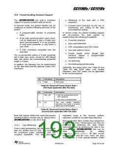
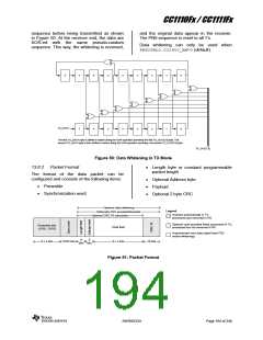
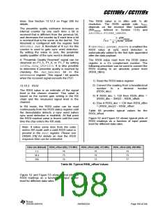
sequence before being transmitted as shown
in Figure 50. At the receiver end, the data are
XOR-ed with the same pseudo-random
sequence. This way, the whitening is reversed,
and the original data appear in the receiver.
The PN9 sequence is reset to all 1’s.
Data whitening can only be used when
PKTCTRL0.CC2400_EN=0(default).
8
7
6
5
4
3
2
1
0
TX_DATA
7
6
5
4
3
2
1
0
The first TX_DATA byte is shifted in before doing the XOR-operation providing the first TX_OUT[7:0] byte. The
second TX_DATA byte is then shifted in before doing the XOR-operation providing the second TX_OUT[7:0] byte.
TX_OUT[7:0]
Figure 50: Data Whitening in TX Mode
13.8.2
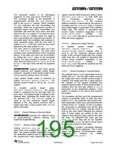
Packet Format
Length byte or constant programmable
packet length
The format of the data packet can be
configured and consists of the following items:
Optional Address byte
Payload
Preamble
Synchronization word
Optional 2 byte CRC
Optional data whitening
Legend:
Optionally FEC encoded/decoded
Optional CRC-16 calculation
Inserted automatically in TX,
processed and removed in RX.
Optional user-provided fields processed in TX,
processed but not removed in RX.
Preamble bits
(1010...1010)
Data field
8 x n bits
Unprocessed user data (apart from FEC
and/or whitening)
8
8
8 x n bits
16/32 bits
16 bits
bits bits
Figure 51: Packet Format
SWRS033H
Page 194 of 246

 TI [ TEXAS INSTRUMENTS ]