CC1110Fx / CC1111Fx
multiple bits, interleaving is used when FEC is
enabled. After de-interleaving, a continuous
span of errors in the received stream will
become single errors spread apart.
In addition, the amount of data transmitted
over the air must be a multiple of the size of
the interleaver buffer (two bytes). The packet
control hardware therefore automatically
inserts one or two extra bytes at the end of the
packet, so that the total length of the data to be
interleaved is an even number. Note that these
extra bytes are invisible to the user, as they
are removed before the received packet enters
the RFDdata register.
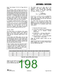
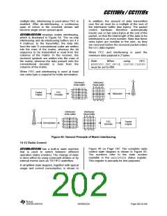
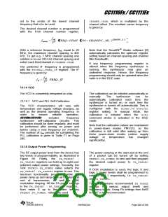
CC1110Fx/CC1111Fx employs matrix interleaving,
which is illustrated in Figure 54. The on-chip
interleaving and de-interleaving buffers are 4 x
4 matrices. In the transmitter, the data bits
from the rate ½ convolutional coder are written
into the rows of the matrix, whereas the bit
sequence to be transmitted is read from the
columns of the matrix. In the receiver, the
received symbols are written into the rows of
the matrix, whereas the data passed onto the
convolutional decoder is read from the
columns of the matrix.
When FEC and interleaving is used the
minimum data payload is 2 bytes.
Note:
When
using
FEC
(MDMCFG1.FEC_EN=1), CLKCON.CLKSPD
must be set to 000.
When FEC and interleaving is used at least
one extra byte is required for trellis termination.
Interleaver
Write buffer
Interleaver
Read buffer
Packet
Engine
FEC
Encoder
Modulator
Interleaver
Write buffer
Interleaver
Read buffer
FEC
Decoder
Packet
Engine
Demodulator
Figure 54: General Principle of Matrix Interleaving
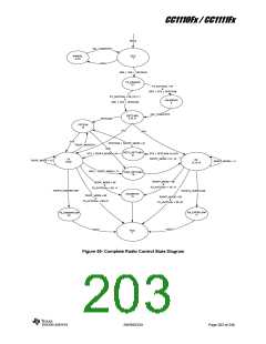
13.12 Radio Control
Figure 48 on Page 187. The complete radio
control state diagram is shown in Figure 55.
The numbers refer to the state number
readable in the MARCSTATE status register.
This register is primarily for test purposes.
CC1110Fx/CC1111Fx has a built-in state machine
that is used to switch between different
operation states (modes). The change of state
is done either by using command strobes or by
internal events such as TX FIFO underflow.
A simplified state diagram, together with typical
usage and current consumption, is shown in
SWRS033H
Page 202 of 246

 TI [ TEXAS INSTRUMENTS ]