CC1110Fx / CC1111Fx
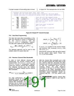
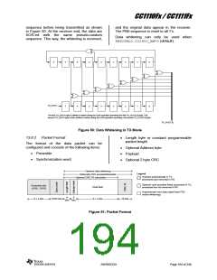
A simple example of transmitting data is shown
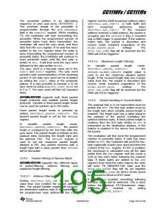
in Figure 49. This example does not use DMA.
; Transmit the following data: 0x02, 0x12, 0x34
; (Assume that the radio has already been configured, the high speed
; crystal oscillator is selected as system clock, and CLKCON.CLKSPD=000)
MOV
JNB
CLR
MOV
JNB
CLR
MOV
JNB
CLR
MOV
RFST,#03H
RFTXRXIF,C1
RFTXRXIF
RFD,#02H
RFTXRXIF,C2
RFTXRXIF
RFD,#12H
RFTXRXIF,C3
RFTXRXIF
; Start TX with STX command strobe
; Wait for interrupt flag telling radio is
; ready to accept data, then write first
; data byte to radio (packet length = 2)
; Wait for radio
;
; Send first byte in payload
; Wait for radio
C1:
C2:
C3:
;
RFD,#34H
; Send second byte in payload
; Done
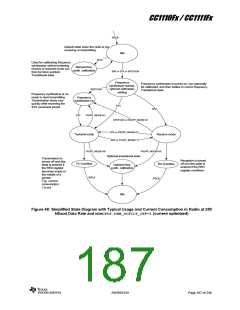
Figure 49: Simple RF Transmit Example
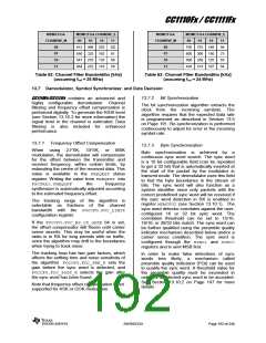
13.5 Data Rate Programming
The data rate used when transmitting, or the
data rate expected in receive is programmed
RDATA 220
DRATE _ E log2
fref
by
the
MDMCFG3.DRATE_M
and
the
RDATA 228
MDMCFG4.DRATE_E configuration registers.
The data rate is given by the formula below.
DRATE _ M
256
fref 2DRATE _ E
256 DRATE _ M 2DRATE _ E
RDATA
fref
If DRATE_M is rounded to the nearest integer
and becomes 256, increment DRATE_E and
use DRATE_M=0.
228
The following approach can be used to find
suitable values for a given data rate:
Note that the maximum data rate will be limited
by the system clock speed. Please see
12.1.5.2 for more details.
13.6 Receiver Channel Filter Bandwidth
In order to meet different channel width
requirements, the receiver channel filter is
programmable. The MDMCFG4.CHANBW_E and
MDMCFG4.CHANBW_M configuration registers
control the receiver channel filter bandwidth.
The following formula gives the relation
between the register settings and the channel
filter bandwidth:
With the channel filter bandwidth set to 500
kHz, the signal should stay within 80% of 500
kHz, which is 400 kHz. Assuming 915 MHz
frequency and ±20 ppm frequency uncertainty
for both the transmitting device and the
receiving
device,
the
total
frequency
uncertainty is ±40 ppm of 915 MHz, which is
±37 kHz. If the whole transmitted signal
bandwidth is to be received within 400 kHz, the
transmitted signal bandwidth should be
maximum 400 kHz - 2·37 kHz, which is 326
kHz.
fref
BWchannel
8 (4 CHANBW_ M)·2CHANBW_ E
The CC1110Fx/CC1111Fx supports channel filter
bandwidths shown in Table 62 and Table 63
respectively.
For best performance, the channel filter
bandwidth should be selected so that the
signal bandwidth occupies at most 80% of the
channel filter bandwidth. The channel centre
tolerance due to crystal accuracy should also
be subtracted from the signal bandwidth. The
following example illustrates this:
SWRS033H
Page 191 of 246

 TI [ TEXAS INSTRUMENTS ]