CC1110Fx / CC1111Fx
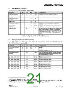
6.3 RF Transmit Section
TA = 25 C, VDD = 3.0 V if nothing else stated. All measurement results are obtained using the
CC1110EM reference designs ([1]) if nothing else is stated.
Parameter
Min
Typ
Max
Unit Condition/Note
Differential impedance as seen from the RF-port (RF_P and
Differential load
impedance
RF_N) towards the antenna. Follow the CC1110EM reference
designs ([1], [2] and [3]) available from the TI website.
315 MHz
122 + j31
116 + j41
86.5 + j43
10
433 MHz
868/915 MHz
Output power,
highest setting
dBm Output power is programmable, and full range is available in
all frequency bands
Output power may be restricted by regulatory limits. See
AN050 [13]. Note that this application note is for CC1101 but the
same limitations apply to CC1110Fx and CC1111Fx as well. For
CC1111Fx see in addition DN016 [14] for information on antenna
solution and additional regulatory restrictions
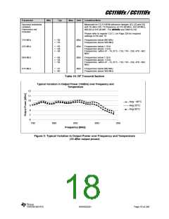
See Figure 3 for typical variation over operating conditions
Delivered to 50 single-ended load via CC1110EM reference
design [3] RF matching network.
Output power,
lowest setting
−30
dBm Output power is programmable and is available across the
entire frequency band
Delivered to 50 single-ended load via CC1110EM reference
design [3] RF matching network.
Harmonics, radiated
Measured on CC1110EM reference designs ([2] and [3]) with
CW, 10 dBm output power
2nd Harm, 433 MHz
3rd Harm, 433 MHz
−51
−42
dBm
dBm The antennas used during the radiated measurements
(SMAFF-433 from R.W. Badland and Nearson S331 868/915)
2nd Harm, 868 MHz
3rd Harm, 868 MHz
−37
−43
dBm
dBm
play a part in attenuating the harmonics
Harmonics, radiated
Measured on [4] CC1111 USB-Dongle Reference Design, with
CW, 10 dBm output power. The chip antenna used during the
radiated measurements play a part in attenuating the
2nd Harm, 868 MHz
3rd Harm, 868 MHz
−55
−55
dBm
harmonics
dBm
Harmonics,
conducted
Measured on CC1110EM reference designs ([1], [2] and [3])
with CW, 10 dBm output power, TX frequency at 315.00 MHz,
433.00 MHz, 868.00 MHz, or 915.00 MHz
315 MHz
433 MHz
< −35
< −52
dBm Frequencies below 960 MHz
Frequencies above 960 MHz
< −44
< −35
dBm Frequencies below 1 GHz
Frequencies above 1 GHz
868 MHz
915 MHz
< −35
< −34
dBm Frequencies above 1 GHz
dBm Frequencies above 1 GHz
SWRS033H
Page 17 of 246

 TI [ TEXAS INSTRUMENTS ]