CC1110Fx / CC1111Fx
The interrupt enables and flags are
summarized below.
configured using a USART Receive/transmit
buffer, UxDBUF, as source or destination
address.
Interrupt enable bits:
Note: For systems requiring setting
UxGCR.CPHA=1, the DMA can not be
used.
USART0 RX : IEN0.URX0IE
USART1 RX : IEN0.URX1IE
USART0 TX : IEN2.UTX0IE
USART1 TX : IEN2.UTX1IE
Interrupt flags:
Refer to Table 51 on Page 107 for an overview
of the DMA triggers.
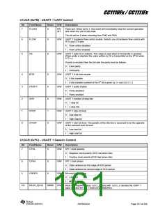
12.14.7 USART Registers
USART0 RX : TCON.URX0IF
USART1 RX : TCON.URX1IF
USART0 TX : IRCON2.UTX0IF
USART1 TX : IRCON2.UTX1IF
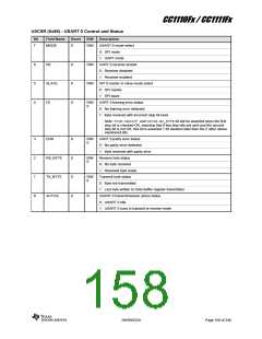
The registers for the USART are described in
this section. For each USART there are five
registers consisting of the following (x refers to
USART number i.e. 0 or 1):
UxCSRUSART x Control and Status
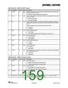
UxUCRUSART x UART Control
UxGCRUSART x Generic Control
12.14.6 USART DMA Triggers
There are two DMA triggers associated with
each USART (URX0, UTX0, URX1, and
UTX1). The DMA triggers are activated by RX
complete and TX complete events i.e. the
same events that might generate USART
interrupt requests. A DMA channel can be
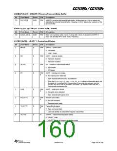
UxDBUF USART x Receive/Transmit
Data Buffer
UxBAUDUSART x Baud Rate Control
SWRS033H
Page 157 of 246

 TI [ TEXAS INSTRUMENTS ]