CC1110Fx / CC1111Fx
asserted and the received data byte is
available in UxDBUF. An interrupt request is
generated if IEN0.URXxIE=1
UxCSR is read. The receiver will check both
stop bits when UxUCR.SPB=1. Note that the
USARTx RX complete CPU interrupt flag,
TCON.URXxIF, and the UxCSR.RX_BYTE bit
will be asserted when the first stop bit is
checked OK. If the second stop bit is not OK,
the framing error bit, UxCSR.FE, will be
asserted. This means that this bit is updated 1
bit duration later than the 2 other above
mentioned bits. The UxCSR.ACTIVEbit will be
de-asserted after the second stop bit (if
UxUCR.SPB=1).
Since UxDBUF
is double-buffered, the
assertion of the USARTx TX complete CPU
interrupt flag (IRCON2.UTXxIF) happens just
after a transmission has been initiated, and is
therefore not safe to use. Instead, the
assertion of the UxCSR.TX_BYTEbit should be
used as an indication on when new data can
be written to UxDBUF. For DMA transfers this
is handled automatically, but with the limitation
that the UxGCR.CPHA bit must be set to zero.
12.14.2 SPI Mode
For
systems
requiring
setting
UxGCR.CPHA=1,the DMA can not be used.
This section describes the SPI mode of
operation for synchronous communication. In
SPI mode, the USART communicates with an
external system through a 3-wire or 4-wire
interface. The interface consists of the pins
MOSI, MISO, SCK and SSN. Refer to Section
12.4 on Page 90 for I/O configuration.
Also note that the USARTx TX complete
interrupt occurs approximately 1 byte period
prior to the USARTx RX complete interrupt.
In SPI master mode, only the MOSI, MISO,
and SCK should be configured as peripherals
(see Section 12.4.6.1 and 12.4.6.2). If the
external slave requires a slave select signal
(SSN) this can be implemented by using a
general-purpose I/O pin and control from SW.
The SPI mode includes the following features:
3-wire (master) and 4-wire SPI interface
Master and slave modes
Configurable SCK polarity and phase
Configurable LSB or MSB first transfer
12.14.2.2 SPI Slave Operation
An SPI byte transfer in slave mode is
controlled by the external system. The data on
the MOSI input is shifted into the receive
register controlled by the serial clock SCK,
which is an input in slave mode. At the same
time the byte in the transmit register is shifted
out onto the MISO output.
The SPI mode is selected when UxCSR.MODE
is set to 0.
In SPI mode, the USART can be configured to
operate either as an SPI master or as an SPI
slave by setting UxCSR.SLAVE to 0 or 1,
respectively.
The UxCSR.ACTIVE bit is set to 1 when SNN
is asserted and cleared when SNN is de-
asserted. The UxCSR.RX_BYTE bit is set to 1
when a byte transfer ends.
12.14.2.1 SPI Master Operation
An SPI byte transfer in master mode is initiated
when the UxDBUF register is written. The
USART generates the SCK signal using the
baud rate generator (see Section 12.14.3) and
shifts the provided byte from the transmit
register onto the MOSI output. At the same
time the receive register shifts in the received
byte from the MISO input pin.
At the end of the transfer, the USARTx RX
complete CPU interrupt flag, TCON.URXxIF, is
asserted and the received data byte is
available in UxDBUF. An interrupt request is
generated if IEN0.URXxIE=1. The USARTx
TX
complete
CPU
interrupt
flag,
IRCON2.UTXxIF, is asserted at the start of
the operation and an interrupt request is
generated if IEN2.UTXxIE=1.
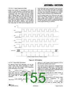
The polarity and clock phase of the serial clock
SCK is selected by UxGCR.CPOL and
UxGCR.CPHA. The order of the byte transfer is
selected by the UxGCR.ORDERbit.
The expected polarity and clock phase of SCK
is selected by UxGCR.CPOLand UxGCR.CPHA
as shown in Figure 41. The expected order of
the byte transfer is selected by the
UxGCR.ORDER bit.
The UxCSR.ACTIVE bit goes high when the
transfer starts and low when the transfer ends.
When the transfer ends, the UxCSR.TX_BYTE
bit is set to 1.
At the end of the transfer, the USARTx RX
complete CPU interrupt flag, TCON.URXxIF, is
SWRS033H
Page 154 of 246

 TI [ TEXAS INSTRUMENTS ]