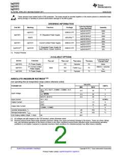
bq51010
bq51011
bq51013
SLVSAT9B –APRIL 2011–REVISED AUGUST 2011
www.ti.com
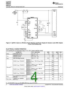
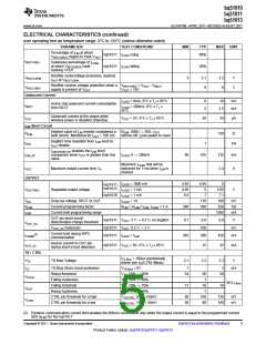
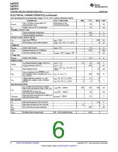
ELECTRICAL CHARACTERISTICS (continued)
over operating free-air temperature range, 0°C to 125°C (unless otherwise noted)
PARAMETER
TEST CONDITIONS
MIN
TYP
24
MAX
UNIT
ms
Time VTS-Bias is active when TS
measurements occur
Synchronous to the
communication period
tTS/CTRL
tTS
Deglitch time for all TS comparators
10
ms
THERMAL PROTECTION
Thermal shutdown temperature
Thermal shutdown hysteresis
OUTPUT LOGIC LEVELS ON /CH
155
20
°C
°C
TJ
VOL
Open drain CHG pin
ISINK = 5mA
500
1
mV
IOFF
CHG leakage current when disabled
VCHG = 20 V, 0°C ≤ TJ ≤ 85°C
µA
COMM PIN
RDS(ON)
fCOMM
Comm1 and Comm2
VRECT = 4V
1.5
Ω
Signaling frequency on COMM pin
Comm pin leakage current
2.00
Kb/s
µA
IOFF
VCOMM1 = 20V, VCOMM2 = 20V
1
CLAMP PIN
RDS(ON)
Adapter Enable
Clamp1 and Clamp2
0.5
Ω
VAD Rising threshold voltage. EN-UVLO
VAD-EN hysteresis, EN-HYS
VAD 0 → 5 V
VAD 5 → 0 V
3.5
3.6
3.8
V
VAD-EN
IAD
400
mV
VRECT = 0V, VAD = 5V, 0°C ≤ TJ
≤ 85°C
Input leakage current
55
μA
Pull-up resistance from AD-EN to OUT
when adapter mode is disabled and VOUT
VAD, EN-OUT
RAD
>
VAD = 0, VOUT = 5
200
350
Ω
Voltage difference between VAD and
VAD-EN when adapter mode is enabled,
EN-ON
VAD = 5V, 0°C ≤ TJ ≤ 85°C
VAD = 9V, 0°C ≤ TJ ≤ 85°C
3
3
4.5
6
5
7
VAD
V
Synchronous Rectifier
IOUT at which the synchronous rectifier
ILOAD 300 → 200mA
ILOAD 200 → 300mA
IAC-VRECT = 250mA
200
225
40
250
mA
mA
V
enters half synchronous mode, SYNC_EN
IOUT
Hysteresis for IOUT,RECT-EN
(full-synchronous mode enabled)
High-side diode drop when the rectifier is in
half synchronous mode
VHS-DIODE
0.7
EN1 and EN2
VIL
Input low threshold for EN1 and EN2
Input high threshold for EN1 and EN2
EN1 and EN2 pull down resistance
0.4
V
V
VIH
1.3
RPD
ADC
VRECT
200
kΩ
Rectified power measurement
0W – 5W of rectified power
±6%
6
Submit Documentation Feedback
Copyright © 2011, Texas Instruments Incorporated
Product Folder Link(s): bq51010 bq51011 bq51013

 TI [ TEXAS INSTRUMENTS ]