bq51010
bq51011
bq51013
www.ti.com
SLVSAT9B –APRIL 2011–REVISED AUGUST 2011
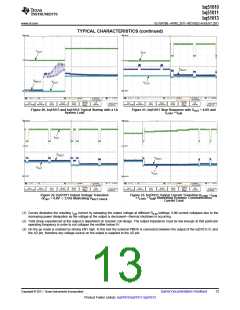
TYPICAL CHARACTERISTICS (continued)
IOUT
IOUT
VRECT
VRECT
VOUT
VOUT
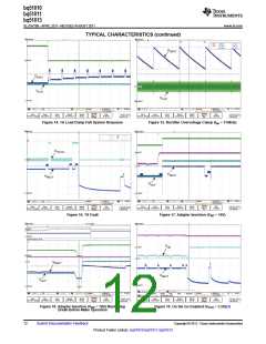
Figure 20. bq51013 and bq51010 Typical Startup with a 1A
System Load
Figure 21. bq51011 Step Response with VOUT = 4.8V and
ILOAD = IILIM
IOUT
VRECT
VRECT
VOUT
VOUT
Figure 22. bq51011 Output Voltage Transition
(VOUT = 4.8V -> 3.5V) Illustrating VRECT-TRACK
Figure 23. bq51011 Output Current Transition (ILOAD < IILIM
≥ ILOAD = IILIM) lIlustrating Dynamic Communication
Current Limit
(1) Curves illustrates the resulting ILIM current by sweeping the output voltage at different RILIM settings. ILIM current collapses due to the
increasing power dissipation as the voltage at the output is decreased—thermal shutdown is occurring.
(2) Total droop experienced at the output is dependent on receiver coil design. The output impedance must be low enough at that particular
operating frequency in order to not collapse the rectifier below 5V.
(3) On the go mode is enabled by driving EN1 high. In this test the external PMOS is connected between the output of the bq5101x IC and
the AD pin, therefore any voltage source on the output is supplied to the AD pin.
Copyright © 2011, Texas Instruments Incorporated
Submit Documentation Feedback
13
Product Folder Link(s): bq51010 bq51011 bq51013

 TI [ TEXAS INSTRUMENTS ]