bq24735
www.ti.com
SLUSAK9 –SEPTEMBER 2011
98
97
96
95
94
93
92
91
90
89
88
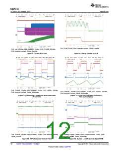
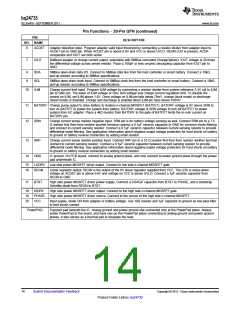
3-cell 12.6 V
4-cell 16.8 V
2-cell 8.4 V
V
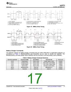
= 20 V,
IN
F = 750 kHz,
L = 4.7 mH
0
0.5
1
1.5
2
2.5
3
3.5
4
4.5
Charge Current
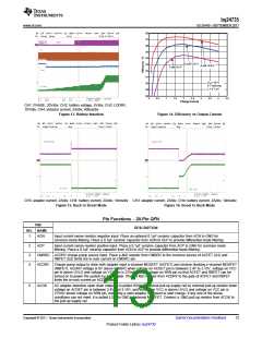
CH1: PHASE, 20V/div, CH2: battery voltage, 5V/div, CH3: LODRV,
10V/div, CH4: inductor current, 2A/div, 400us/div
Figure 13. Battery Insertion
Figure 14. Efficiency vs Output Current
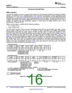
CH3: adapter current, 2A/div, CH4: battery current, 2A/div, 10ms/div CH3: adapter current, 2A/div, CH4: battery current, 2A/div, 10ms/div
Figure 15. Buck to Boost Mode Figure 16. Boost to Buck Mode
Pin Functions – 20-Pin QFN
PIN
DESCRIPTION
NO. NAME
1
2
3
4
ACN
Input current sense resistor negative input. Place an optional 0.1µF ceramic capacitor from ACN to GND for
common-mode filtering. Place a 0.1µF ceramic capacitor from ACN to ACP to provide differential mode filtering.
ACP
Input current sense resistor positive input. Place a 0.1µF ceramic capacitor from ACP to GND for common-mode
filtering. Place a 0.1µF ceramic capacitor from ACN to ACP to provide differential-mode filtering.
CMSRC ACDRV charge pump source input. Place a 4kΩ resistor from CMSRC to the common source of ACFET (Q1) and
RBFET (Q2) limits the in-rush current on CMSRC pin.
ACDRV Charge pump output to drive both adapter input n-channel MOSFET (ACFET) and reverse blocking n-channel MOSFET
(RBFET). ACDRV voltage is 6V above CMSRC when voltage on ACDET pin is between 2.4V to 3.15V, voltage on VCC
pin is above UVLO and voltage on VCC pin is 275mV above voltage on SRN pin so that ACFET and RBFET can be
turned on to power the system by AC adapter. Place a 4kΩ resistor from ACDRV to the gate of ACFET and RBFET
limits the in-rush current on ACDRV pin.
5
ACOK
AC adapter detection open drain output. It is pulled HIGH to external pull-up supply rail by external pull-up resistor when
voltage on ACDET pin is between 2.4V and 3.15V, and voltage on VCC is above UVLO and voltage on VCC pin is
275mV above voltage on SRN pin, indicating a valid adapter is present to start charge. If any one of the above
conditions can not meet, it is pulled LOW to GND by internal MOSFET. Connect a 10kΩ pull up resistor from ACOK to
the pull-up supply rail.
Copyright © 2011, Texas Instruments Incorporated
Submit Documentation Feedback
13
Product Folder Link(s) :bq24735

 TI [ TEXAS INSTRUMENTS ]