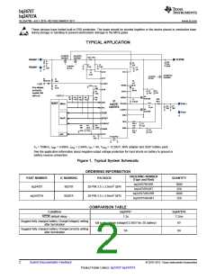
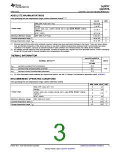
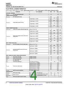
bq24707
bq24707A
SLUSA78B –JULY 2010–REVISED MARCH 2011
www.ti.com
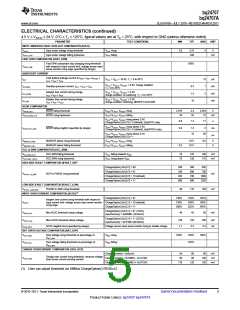
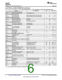
ELECTRICAL CHARACTERISTICS (continued)
4.5 V ≤ V(VCC) ≤ 24 V, 0°C ≤ TJ ≤ 125°C, typical values are at TA = 25°C, with respect to GND (unless otherwise noted)
PARAMETER
TEST CONDITIONS
MIN
TYP
MAX
UNIT
CHARGE UNDER-CURRENT COMPARATOR (CHG_UCP)
VUCP_FALL
Charge under current falling threshold
VSRP falling towards VSRN
1
5
9
mV
LIGHT LOAD COMPARATOR (LIGHT_LOAD)
VLL_FALL
Light load falling threshold
Light load rising hysteresis
Measure voltage drop across current sensing resistor
Measure voltage drop across current sensing resistor
1.25
1.25
mV
mV
VLL_RISE_HYST
BATTERY LOWV COMPARATOR (BAT_LOWV)
VBATLV_FALL
VBATLV_RHYST
IBATLV
Battery LOWV falling threshold
Battery LOWV rising hysteresis
Battery LOWV charge current limit
VSRN falling
2.4
2.5
200
0.5
2.6
V
mV
A
VSRN rising
10mΩ current sensing resistor
THERMAL SHUTDOWN COMPARATOR (TSHUT)
TSHUT
Thermal shutdown rising temperature
Thermal shutdown hysteresis, falling
Temperature rising
Temperature falling
155
20
°C
°C
TSHUT_HYS
ILIM COMPARATOR
VILIM_FALL
ILIM as CE falling threshold
ILIM as CE rising threshold
VILIM falling
VILIM rising
60
90
75
90
mV
mV
VILIM_RISE
105
120
LOGIC INPUT (SDA, SCL)
VIN_
VIN_
IIN_
Input low threshold
0.8
1
V
V
LO
HI
Input high threshold
Input bias current
2.1
V = 7 V
–1
μA
LEAK
LOGIC OUTPUT OPEN DRAIN (ACOK, SDA, IFAULT, CMPOUT)
VOUT_
Output saturation voltage
Leakage current
5 mA drain current
V = 7 V
500
1
mV
LO
IOUT_
–1
–1
1
μA
LEAK
ANALOG INPUT (ACDET, ILIM)
IIN_ Input bias current
V = 7 V
1
7
μA
μA
LEAK
ANALOG INPUT (CMPIN has 50kΩ series resistor and 2000kΩ pull down resistor)
IIN_LEAK
Input bias current
V = 7 V
3.5
PWM OSCILLATOR
FSW
PWM switching frequency
PWM increase frequency
PWM decrease frequency
ChargeOption() bit [9] = 0 (default)
ChargeOption() bit [10:9] = 11
ChargeOption() bit [10:9] = 01
600
665
465
750
885
615
900
1100
765
kHz
kHz
kHz
FSW+
FSW–
PWM HIGH SIDE DRIVER (HIDRV)
RDS_HI_ON
High side driver (HSD) turn-on resistance
V
V
V
BTST – VPH = 5.5 V, I = 10mA
12
0.65
4.3
20
1.3
4.7
Ω
Ω
V
RDS_HI_OFF
VBTST_REFRESH
High side driver turn-off resistance
BTST – VPH = 5.5 V, I = 10mA
Bootstrap refresh comparator threshold voltage
BTST – VPH when low side refresh pulse is requested
3.85
PWM LOW SIDE DRIVER (LODRV)
RDS_LO_ON
Low side driver (LSD) turn-on resistance
VREGN = 6 V, I = 10 mA
VREGN = 6 V, I = 10 mA
15
25
Ω
Ω
RDS_LO_OFF
Low side driver turn-off resistance
0.9
1.4
PWM DRIVER TIMING
tLOW_HIGH
Driver dead time from low side to high side
Driver dead time from high side to low side
20
20
ns
ns
tHIGH_LOW
INTERNAL SOFT START
ISTEP Soft start step size
tSTEP
In CCM mode, 10mΩ current sense resistor
In CCM mode, 10mΩ current sense resistor
64
mA
Soft start step time
240
μs
(2)
INDEPENDENT COMPARATOR
VIC_REF1
VIC_REF2
RS
Comparator reference
ChargeOption() bit [4] = 0, rising edge (default)
ChargeOption() bit [4] = 1, rising edge
0.585
2.375
0.6
2.4
0.615
2.425
V
V
Comparator reference
Series resistor
50
kΩ
kΩ
RDOWN
Pull down resistor
2000
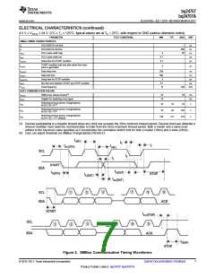
(2) User can adjust threshold via SMBus ChargeOption() REG0x12.
6
Submit Documentation Feedback
© 2010–2011, Texas Instruments Incorporated
Product Folder Link(s): bq24707 bq24707A

 TI [ TEXAS INSTRUMENTS ]