bq24707
bq24707A
SLUSA78B –JULY 2010–REVISED MARCH 2011
www.ti.com
These devices have limited built-in ESD protection. The leads should be shorted together or the device placed in conductive foam
during storage or handling to prevent electrostatic damage to the MOS gates.
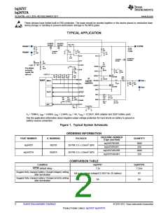
TYPICAL APPLICATION
Q1 (RBFET)
Si4435DDY
Q2 (ACFET)
Si4435DDY
RAC 10m?
Adapter +
Adapter -
SYSTEM
Ri
2?
Total
Csys
220µF
R9
10Ω
C1
0.1µF
C3
0.1µF
Ci
2.2µF
Controlled
By Host
C5
1µF
ACN
VCC
C2
0.1µF
Q5 (BATFET)
Si4435DDY
Controlled
By Host
ACP
D2
RB751V40
R1
430k
C6
1µF
ACDET
+1.5V
REGN
BTST
R2
66.5k
R8
100k
If no adapter,
and Iout is
needed, this
rail is on
D1
BAT54
ILIM
C9
10uF
C8
10uF
R7
316k
+3.3V
Q3
Sis412DN
R3
10k
R4
10k
R6
10k
R10
10k
R5
10k
HIDRV
PHASE
RSR
10m?
C7
0.047µF
U1
bq24707
bq24707A
SDA
HOST
SMBus
Pack +
L1
4.7µH
C10
10µF
C11
10µF
SCL
Q4
Sis412DN
LODRV
GND
Pack -
ACOK
IFAULT
CMPOUT
CMPIN
IOUT
Dig I/O
SRP
SRN
R14
*
C13
0.1µF
R12
100k
R11
39.2k
R13
3.01M
10Ω
C14
0.1µF
R15
*
7.5Ω
ADC
C4
100p
PowerPad
Fs = 750kHz, Iadpt = 4.096A, Ichrg = 2.944A, Ilim = 4A, Vchrg = 12.592V, 90W adapter and 3S2P battery pack
See the application information about negative output voltage protection for hard shorts on battery to ground or
battery reverse connection.
Figure 1. Typical System Schematic
ORDERING INFORMATION
ORDERING NUMBER
PART NUMBER
IC MARKING
PACKAGE
QUANTITY
(Tape and Reel)
bq24707RGRR
bq24707RGRT
bq24707ARGRR
bq24707ARGRT
3000
250
bq24707
BQ707
20-PIN 3.5 x 3.5mm2 QFN
3000
250
bq24707A
BQ07A
20-PIN 3.5 x 3.5mm2 QFN
COMPARISON TABLE
Condition
bq24707
bq24707A
ACOK default delay
1.3s
1.2ms
Suggest fully charged battery ChargeVoltage() setting
after termination
full scale charge voltage(12.592V for 3S battery)
0A
0V
0A
Suggest fully charged battery ChargeCurrent() setting
after termination
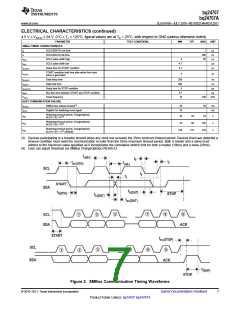
2
Submit Documentation Feedback
© 2010–2011, Texas Instruments Incorporated
Product Folder Link(s): bq24707 bq24707A

 TI [ TEXAS INSTRUMENTS ]