ꢀ ꢁ ꢂ ꢃꢄ ꢅ ꢂꢆ ꢀ ꢁ ꢂ ꢃꢄꢅ ꢇ
SLUS553D − MAY 2003 − REVISED JULY 2005
Softstart
Softstart is provided to ensure an orderly start-up when the PWM is enabled. When the PWM controller is
disabled (ENABLE = Low), the 100-µA current source pullup is disabled and the COMP pin is actively pulled
down to GND. Disabling the 100-µA pullup reduces current drain when the PWM is disabled. When the
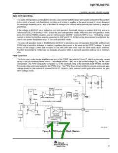
bq24702/bq24703 PWM is enabled (ENABLE = High), the COMP pin is released and the 100-µA pullup is
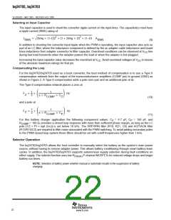
enabled (refer to Figure 2). The voltage on the COMP pin increases as the pullup charges the external
compensation network connected to the COMP pin. As the voltage on the COMP pin increases the PWM duty
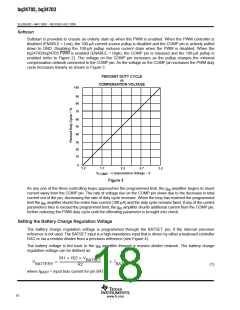
cycle increases linearly as shown in Figure 3.
PERCENT DUTY CYCLE
vs
COMPENSATION VOLTAGE
100
90
80
70
60
50
40
30
20
10
0
1.2
1.7
2.2
2.7
3.2
V
− Compensation Voltage − V
COMP
Figure 3
As any one of the three controlling loops approaches the programmed limit, the g amplifier begins to shunt
m
current away from the COMP pin. The rate of voltage rise on the COMP pin slows due to the decrease in total
current out of the pin, decreasing the rate of duty cycle increase. When the loop has reached the programmed
limit the g amplifier shunts the entire bias current (100 µA) and the duty cycle remains fixed. If any of the control
m
parameters tries to exceed the programmed limit, the g amplifier shunts additional current from the COMP pin,
m
further reducing the PWM duty cycle until the offending parameter is brought into check.
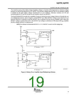
Setting the Battery Charge Regulation Voltage
The battery charge regulation voltage is programmed through the BATSET pin, if the internal precision
reference is not used. The BATSET input is a high-impedance input that is driven by either a keyboard controller
DAC or via a resistor divider from a precision reference (see Figure 4).
The battery voltage is fed back to the g amplifier through a resistor divider network. The battery charge
m
regulation voltage can be defined as:
(
)
R1 ) R2 V
BATSET
V
+
V ) I
R1
BATTERY
BATP
R2
(1)
where I
= input bias current for pin BATP
BATP
18
www.ti.com

 TI [ TEXAS INSTRUMENTS ]