ꢀ
ꢁ
ꢂ
ꢃ
ꢄ
ꢅ
ꢂ
ꢆ
ꢀ
ꢁ
ꢂ
ꢃ
ꢄ
ꢅ
ꢇ
SLUS553D − MAY 2003 − REVISED JULY 2005
Selecting an Input Capacitor
The input capacitor is used to shunt the converter ripple current on the input lines. The capacitor(s) must have
a ripple current (RMS) rating of:
2
2
+ Ǹ[
(
)]
[
]
(
)
I
Ichg 1–D D ) Ichg D 1–D
A
RMS
RMS
(9)
In addition to shunting the converter input ripple when the PWM is operating, the input capacitor also acts as
part of an LC filter, where the inductance component is defined by the ac adapter cable inductance and board
trace inductance from adapter connector to filter capacitor. Overshoot conditions can be observed at V
during fast load transients when the adapter powers the load or when the adapter is hot-plugged .
line
CC
Increasing the input capacitor value decreases the overshoot at V . Avoid overshoot voltages at V
CC
of the absolute maximum ratings for that pin.
in excess
CC
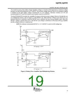
Compensating the Loop
For the bq24702/bq24703 used as a buck converter, the best method of compensation is to use a Type II
compensation network from the output of the transconductance amplifiers (COMP pin) to ground (GND) as
shown in Figure 2. A Type II compensation adds a pole-zero pair and an additional pole at dc.
The Type II compensation network places a zero at
1
2
1
F
+
ǒ
ǒ
Ǔ
Ǔ
Hz
Hz
Z
p R
C
COMP
Z
(10)
(11)
and a pole at
1
2
1
F
+
P
p R
C
COMP
P
For this battery charger application the following component values: C = 4.7 µF, C = 150 pF, and
Z
P
R
= 100 Ω, provides a closed loop response with more than sufficient phase margin, as long as the LC
COMP
pole [1/2 × PI × sqrt (l×c)] is set below 10 kHz. The SRP/SRN filter (R19, R21, C8) and ACP/ACN filter
(R13/R15/C3) are required to filter noise associated with the PWM switching. To avoid adding secondary poles
to the PWM closed loop system those filters should be set with cutoff frequencies higher than 1 kHz.
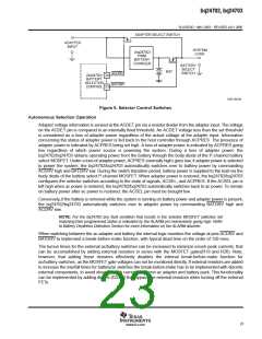
Selector Operation
The bq24702/bq24703 allows the host controller to manually select the battery as the system’s main power
source, without having to remove adapter power. This allows battery conditioning through smart battery learn
cycles. In addition, the bq24702/bq24703 supports autonomous supply selection during fault conditions on
either supply. The selector function uses low R
battery run times.
P-channel MOSFETs for reduced voltage drops and longer
DS(on)
NOTE: Selection of battery power whether manual or automatic results in the suspension of battery
charging.
22
www.ti.com

 TI [ TEXAS INSTRUMENTS ]