ꢀ ꢁꢂ ꢃ ꢄ ꢅ ꢂ ꢆ ꢀꢁ ꢂꢃ ꢄꢅ ꢇ
SLUS553D − MAY 2003 − REVISED JULY 2005
APPLICATION INFORMATION
Programming the Thresholds
The input-referenced thresholds for battery depleted, ac detection and charge voltage are defined by
dimensioning the external dividers connected to pins BATDEP, ACDET and BATP. This calculation is simple,
and consists of assuming that when the input voltage equals the desired threshold value the voltage at the
related pin is equal to the pin internal reference voltage:
Vinput = Vpin × (1 + Kres)
where:
Vinput = Target threshold, referenced to input signal
Vpin = Internal reference(1.196 V for BATP; 1.246 V for BATDEP, ACDET)
Kres = External resistive divider gain ( for instance: R24/R25 for BATP)
When using external dividers with high absolute value the input bias currents for those pins must be included
in the threshold calculation. On the bq24702/3 the input bias currents increase the actual value for the threshold
voltage, when compared to the values calculated using the internal references and divider gain only:
Vinput = Vpin × (1+Kres) + Vbias
The increase on the threshold voltage is given by:
Vbias = Rdiv × Ipin
where:
Vbias = Voltage increase due to pin bias current
Rdiv = External resistor value for resistor connected from pin to input voltage
Ipin = Maximum pin leakage current
The effect of IB can be reduced if the resistor values are decreased.
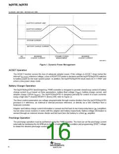
Dynamic Power Management
The dynamic power management (DPM) feature allows a cost effective choice of an ac wall-adapter that
accommodates 90% of the system’s operating-current requirements. It minimizes battery charge time by
allocating available power to charge the battery (i.e. I
= I
− I
). If the system plus battery charge
BAT
ADPT
SYS
current exceeds the adapter current limit, as shown in Figure 1, the DPM feature reduces the battery charge
current to maintain an overall input current consumption within user defined power capability of the wall-adapter.
As the system’s current requirements decrease, additional current can be directed to the battery, thereby
increasing battery charge current and minimizing battery charge time.
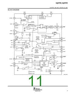
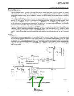
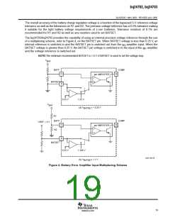
The DPM feature is inherently designed into the PWM controller by inclusion of the three control loops,
battery-charge regulation voltage, battery-charge current, and adapter-charge current, refer to Figure 2. If any
of the three user programmed limits are reached, the corresponding control loop commands the PWM controller
to reduce duty cycle, thereby reducing the battery charge current.
15
www.ti.com

 TI [ TEXAS INSTRUMENTS ]