bq24296
bq24297
www.ti.com
SLUSBP6A –SEPTEMBER 2013–REVISED OCTOBER 2013
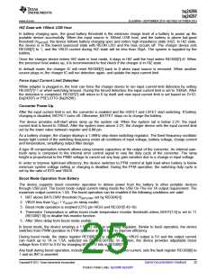
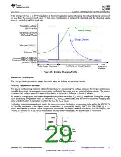
If the charger device is in DPM regulation or thermal regulation during charging, the actual charging current will
be less than the programmed value. In this case, termination is temporarily disabled and the charging safety
timer is counted at half the clock rate.
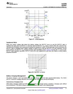
Regulation Voltage
(3.5V – 4.4V)
Battery Voltage
Fast Charge Current
(500mA-3008mA)
Charge Current
V
BAT_LOWV (2.8V/3V)
V
BAT_SHORT (2V)
I
PRECHARGE (128mA-2048mA)
TERMINATION (128mA-2048mA)
BATSHORT (100mA)
I
I
Fast Charge and Voltage Regulation
Trickle Charge Pre-charge
Safety Timer
Expiration
Figure 29. Battery Charging Profile
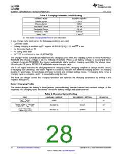
Thermistor Qualification
The charger device provides a single thermistor input for battery temperature monitor.
Cold/Hot Temperature Window
The device continuously monitors battery temperature by measuring the voltage between the TS pin and ground,
typically determined by a negative temperature coefficient thermistor and an external voltage divider. The device
compares this voltage against its internal thresholds to determine if charge or boost is allowed.
To initiate a charge cycle, the battery temperature must be within the VLTF to VHTF thresholds. During the charge
cycle the battery temperature must be within the VLTF to VTCO thresholds, else the device suspends charging and
waits until the battery temperature is within the VLTF to VHTF range.
For battery protection during boost mode, the device monitors the battery temperature to be within the VBCOLDx
to VBHOTx thresholds unless boost mode temperature is disabled by setting BHOT bits (REG06[3:2]) to 11.
When temperature is outside of the temperature thresholds, the boost mode is suspended and REG08[7:6] bits
(VBUS_STAT) are set to 00. Once temperature returns within thresholds, the boost mode is recovered.
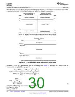
REGN
bq24296
bq24297
RT1
TS
RTH
RT2
103AT
Figure 30. TS Resistor Network
Copyright © 2013, Texas Instruments Incorporated
Submit Documentation Feedback
29
Product Folder Links: bq24296 bq24297

 TI [ TEXAS INSTRUMENTS ]