bq24296
bq24297
www.ti.com
SLUSBP6A –SEPTEMBER 2013–REVISED OCTOBER 2013
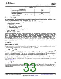
Table 7. STAT Pin State
CHARGING STATE
STAT
LOW
Charging in progress (including recharge)
Charging complete
HIGH
Sleep mode, charge disable
HIGH
Charge suspend (Input over-voltage, TS fault, timer fault, input
or system over-voltage)
blinking at 1Hz
Interrupt to Host (INT)
In some applications, the host does not always monitor the charger operation. The INT notifies the system on the
device operation. The following events will generate 256us INT pulse.
1. USB/adapter source identified (through PSEL or DPDM detection, and OTG pin)
2. Good input source detected
–
–
–
not in sleep
VBUS below VACOV threshold
current limit above IBADSRC
3. Input removed or VBUS above VACOV threshold
4. Charge Complete
5. Any FAULT event in REG09
For the first four events, INT pulse is always generated. For the last event, when a fault occurs, the charger
device sends out INT and latches the fault state in REG09 until the host reads the fault register. If a prior fault
exists, the charger device would not send any INT upon new faults except NTC fault (REG09[2:0]). The NTC
fault is not latched and always reports the current thermistor conditions. In order to read the current fault status,
the host has to read REG09 two times consecutively. In order to read the current fault status, the host has to
read REG09 two times consecutively. The 1st reads fault register status from the last read and the 2nd reads the
current fault register status.
Protections
Input Current Limit on ILIM
For safe operation, the device has an additional hardware pin on ILIM to limit maximum input current on ILIM pin.
The input maximum current is set by a resistor from ILIM pin to ground as:
1V
I
=
´KLIM
INMAX
RILIM
(2)
The actual input current limit is the lower value between ILIM setting and register setting (REG00[2:0]). For
example, if the register setting is 111 for 3A, and ILIM has a 316Ω resistor to ground for 1.5A, the input current
limit is 1.5A. ILIM pin can be used to set the input current limit rather than the register settings.
The device regulates ILIM pin at 1V. If ILIM voltage exceeds 1V, the device enters input current regulation (Refer
to Dynamic Power Path Management section).
The voltage on ILIM pin is proportional to the input current. ILIM pin can be used to monitor the input current
following Equation 3:
V
ILIM
I
=
´I
INMAX
IN
1V
(3)
For example, if ILIM pin sets 2A, and the ILIM voltage is 0.75V, the actual input current 1.5A. If ILIM pin is open,
the input current is limited to zero since ILIM voltage floats above 1V. If ILIM pin is short, the input current limit is
set by the register.
Copyright © 2013, Texas Instruments Incorporated
Submit Documentation Feedback
33
Product Folder Links: bq24296 bq24297

 TI [ TEXAS INSTRUMENTS ]