bq24296
bq24297
SLUSBP6A –SEPTEMBER 2013–REVISED OCTOBER 2013
www.ti.com
Power Path Management
The device accommodates a wide range of input sources from USB, wall adapter, to car battery. The device
provides automatic power path selection to supply the system (SYS) from input source (VBUS), battery (BAT), or
both.
Narrow VDC Architecture
The device deploys Narrow VDC architecture (NVDC) with BATFET separating system from battery. The
minimum system voltage is set by REG01[3:1]. Even with a fully depleted battery, the system is regulated above
the minimum system voltage (default 3.5V).
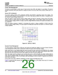
When the battery is below minimum system voltage setting, the BATFET operates in linear mode (LDO mode),
and the system is 150mV above the minimum system voltage setting. As the battery voltage rises above the
minimum system voltage, BATFET is fully on and the voltage difference between the system and battery is the
VDS of BATFET.
When the battery charging is disabled or terminated, the system is always regulated at 150mV above the
minimum system voltage setting. The status register REG08[0] goes high when the system is in minimum system
voltage regulation.
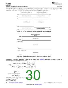
4.5
4.3
Charge Enabled
4.1
Charge Disabled
SYS
(V)
3.9
3.7
3.5
Minimum System Voltage
3.3
3.1
2.7 2.9 3.1 3.3 3.5 3.7 3.9 4.1 4.3
BAT (V)
Figure 26. V(SYS) vs V(BAT)
Dynamic Power Management
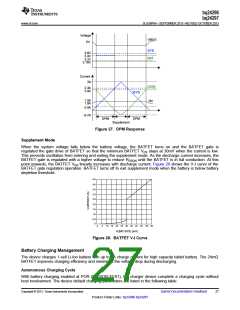
To meet maximum current limit in USB spec and avoid over loading the adapter, the device features Dynamic
Power Management (DPM), which continuously monitors the input current and input voltage.
When input source is over-loaded, either the current exceeds the input current limit (REG00[2:0]) or the voltage
falls below the input voltage limit (REG00[6:3]). The device then reduces the charge current until the input current
falls below the input current limit and the input voltage rises above the input voltage limit.
When the charge current is reduced to zero, but the input source is still overloaded, the system voltage starts to
drop. Once the system voltage falls below the battery voltage, the device automatically enters the supplement
mode where the BATFET turns on and battery starts discharging so that the system is supported from both the
input source and battery.
During DPM mode (either VINDPM or IINDPM), the status register REG08[3] will go high.
Figure 27 shows the DPM response with 5V/1.2A adapter, 3.2V battery, 2.0A charge current and 3.4V minimum
system voltage setting.
26
Submit Documentation Feedback
Copyright © 2013, Texas Instruments Incorporated
Product Folder Links: bq24296 bq24297

 TI [ TEXAS INSTRUMENTS ]