bq24170
bq24172
www.ti.com
SLUSAD2A –NOVEMBER 2010–REVISED NOVEMBER 2010
APPLICATION INFORMATION
INDUCTOR SELECTION
The bq24170/72 has a 1600-kHz switching frequency to allow the use of small inductor and capacitor values.
Inductor saturation current should be higher than the charging current (ICHG) plus half the ripple current (IRIPPLE):
ISAT ³ ICHG+(1/2)IRIPPLE
(13)
Inductor ripple current depends on input voltage (VIN), duty cycle (D = VOUT/VIN), switching frequency (fs), and
inductance (L):
V
IN ´D´(1- D)
IRIPPLE
=
fs × L
(14)
The maximum inductor ripple current happens with D = 0.5 or close to 0.5. Usually inductor ripple is designed in
the range of 20% to 40% of the maximum charging current as a trade-off between inductor size and efficiency for
a practical design.
INPUT CAPACITOR
The input capacitor should have enough ripple current rating to absorb input switching ripple current. The worst
case RMS ripple current is half of the charging current when duty cycle is 0.5. If the converter does not operate
at 50% duty cycle, then the worst case capacitor RMS current ICIN occurs where the duty cycle is closest to 50%
and can be estimated by the following equation:
ICIN = ICHG ´ D´(1- D)
(15)
A low ESR ceramic capacitor such as X7R or X5R is preferred for the input decoupling capacitor and should be
placed as close as possible to the drain of the high-side MOSFET and source of the low-side MOSFET. The
voltage rating of the capacitor must be higher than the normal input voltage level. A 25V rating or higher
capacitor is preferred for a 15V input voltage. A 20mF capacitance is suggested for a typical 3A to 4A charging
current.
OUTPUT CAPACITOR
The output capacitor also should have enough ripple current rating to absorb output switching ripple current. The
output capacitor RMS current ICOUT is given as:
IRIPPLE
ICOUT
=
» 0.29´IRIPPLE
2 ´
3
(16)
The output capacitor voltage ripple can be calculated as follows:
æ
ö
÷
÷
ø
VOUT
VOUT
DVO
=
ç1-
8LCfs2
ç
è
V
IN
(17)
At certain input/output voltages and switching frequencies, the voltage ripple can be reduced by increasing the
output filter LC.
The bq24170/72 has an internal loop compensator. To achieve good loop stability, the resonant frequency of the
output inductor and output capacitor should be designed between 15 kHz and 25 kHz. The preferred ceramic
capacitor has a 25V or higher rating, X7R or X5R.
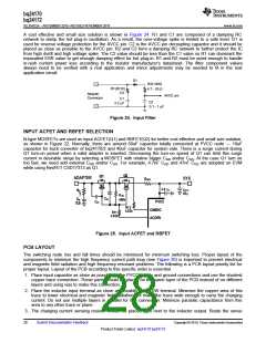
INPUT FILTER DESIGN
During adapter hot plug-in, the parasitic inductance and the input capacitor from the adapter cable form a second
order system. The voltage spike at the AVCC pin may be beyond the IC maximum voltage rating and damage
the IC. The input filter must be carefully designed and tested to prevent an over-voltage event on the AVCC pin.
There are several methods to damping or limiting the over-voltage spike during adapter hot plug-in. An
electrolytic capacitor with high ESR as an input capacitor can damp the over-voltage spike well below the IC
maximum pin voltage rating. A high current capability TVS Zener diode can also limit the over-voltage level to an
IC safe level. However, these two solutions may not be lowest cost or smallest size.
Copyright © 2010, Texas Instruments Incorporated
Submit Documentation Feedback
27
Product Folder Link(s): bq24170 bq24172

 TI [ TEXAS INSTRUMENTS ]