bq24170
bq24172
www.ti.com
SLUSAD2A –NOVEMBER 2010–REVISED NOVEMBER 2010
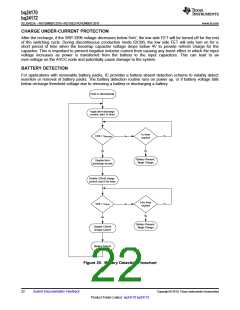
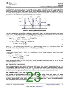
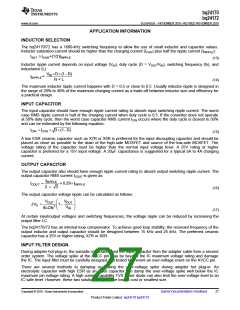
Once the device has powered up, a 8-mA discharge current is applied to the SRN terminal. If the battery voltage
falls below the LOWV threshold within 1 second, the discharge source is turned off, and the charger is turned on
at low charge current (125mA). If the battery voltage gets up above the recharge threshold within 500ms, there is
no battery present and the cycle restarts. If either the 500ms or 1 second timer time out before the respective
thresholds are hit, a battery is detected and a charge cycle is initiated.
Battery
Absent
Battery
Absent
VBAT_RE
VRECH
Battery
Present
VLOW
Figure 21. Battery Detect Timing Diagram
Care must be taken that the total output capacitance at the battery node is not so large that the discharge current
source cannot pull the voltage below the LOWV threshold during the 1 second discharge time. The maximum
output capacitances can be calculated according to the following equations:
IDISCH ´ tDISCH
CMAX
=
(for bq24170)
(4.1 V - 2.9 V) ´ Number of cells
IDISCH ´ tDISCH
(7)
CMAX
=
(for bq24172)
é
ù
ú
û
R2
R1
(2.05 V - 1.45 V) ´ 1+
ê
ë
(8)
Where CMAX is the maximum output capacitance, IDISCH is the discharge current, tDISCH is the discharge time, and
R2 and R1 are the voltage feedback resistors from the battery to the FB pin.
Example
For a 3-cell Li+ charger, with R2 = 500kΩ, R1 = 100kΩ (giving 12.6V for voltage regulation), IDISCH = 8mA, tDISCH
= 1 second.
8 mA ´ 1 sec
CMAX
=
= 2.2 mF
500 kW
100 kW
é
ù
0.6 V ´ 1+
ê
ú
ë
û
(9)
Based on these calculations, no more than 2200 µF should be allowed on the battery node for proper operation
of the battery detection circuit.
BATTERY SHORT PROTECTION
When SRN pin voltage is lower than 2V it is considered as battery short condition during charging period. The
charger will shut down immediately for 1ms, then soft start back to the charging current the same as precharge
current. This prevents high current may build in output inductor and cause inductor saturation when battery
terminal is shorted during charging. The converter works in non-synchronous mode during battery short.
BATTERY OVER-VOLTAGE PROTECTION
The converter will not allow the high-side FET to turn-on until the battery voltage goes below 102% of the
regulation voltage. This allows one-cycle response to an over-voltage condition – such as occurs when the load
is removed or the battery is disconnected. A total 6mA current sink from SRP/SRN to AGND allows discharging
the stored output inductor energy that is transferred to the output capacitors. If battery over-voltage condition
lasts for more than 30ms, charge is disabled.
Copyright © 2010, Texas Instruments Incorporated
Submit Documentation Feedback
23
Product Folder Link(s): bq24170 bq24172

 TI [ TEXAS INSTRUMENTS ]