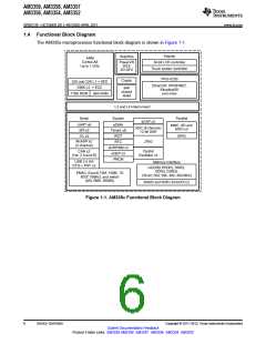
AM3359, AM3358, AM3357
AM3356, AM3354, AM3352
SPRS717F –OCTOBER 2011–REVISED APRIL 2013
www.ti.com
Locate Addresses of Data Errors from
Syndrome Polynomials Generated Using
a BCH Algorithm
Supports 4-Bit, 8-Bit, and 16-Bit per 512-
byte Block Error Location Based on BCH
Algorithms
Week) and Time (Hours-Minutes-Seconds)
Information
– Internal 32.768-kHz Oscillator, RTC Logic
and 1.1-V Internal LDO
– Independent Power-on-Reset
(RTC_PWRONRSTn) Input
•
• Programmable Real-Time Unit and Industrial
Communication Subsystem (PRU-ICSS)
– Dedicated Input Pin (EXT_WAKEUP) for
External Wake Events
– Programmable Alarm Can be Used to
Generate Internal Interrupts to the PRCM (for
Wake Up) or Cortex-A8 (for Event
Notification)
– Supports protocols such as EtherCAT®,
PROFIBUS, PROFINET, EtherNet/IP™, and
more
– Peripherals Inside the PRU-ICSS
•
One UART Port with Flow Control Pins,
Supports Up to 12 Mbps
Two MII Ethernet Ports that Support
Industrial Ethernet, such as EtherCAT
– Programmable Alarm Can be Used with
External Output (PMIC_POWER_EN) to
Enable the Power Management IC to Restore
Non-RTC Power Domains
•
• Peripherals
•
•
One MDIO Port
One Enhanced Capture (eCAP) Module
– Up to Two USB 2.0 High-Speed OTG Ports
with Integrated PHY
– Up to Two Industrial Gigabit Ethernet MACs
(10, 100, 1000 Mbps)
• Power Reset and Clock Management (PRCM)
Module
– Controls the entry and Exit of Stand-By and
Deep-Sleep Modes
– Responsible for Sleep Sequencing, Power
Domain Switch-Off Sequencing, Wake-Up
Sequencing and Power Domain Switch-On
Sequencing
•
•
Integrated Switch
Each MAC Supports MII, RMII, RGMII and
MDIO Interfaces
•
•
Ethernet MACs and Switch Can Operate
Independent of Other Functions
IEEE 1588v2 Precision Time Protocol
(PTP)
– Clocks
•
•
•
Integrated 15-35 MHz High-Frequency
Oscillator Used to Generate a Reference
Clock for Various System and Peripheral
Clocks
Supports Individual Clock Enable and
Disable Control for Subsystems and
Peripherals to Facilitate Reduced Power
Consumption
Five ADPLLs to Generate System Clocks
(MPU Subsystem, DDR Interface, USB
and Peripherals [MMC and SD, UART,
SPI, I2C], L3, L4, Ethernet, GFX [SGX530],
LCD Pixel Clock)
– Up to Two Controller-Area Network (CAN)
Ports
•
Supports CAN Version 2 Parts A and B
– Up to Two Multichannel Audio Serial Ports
(McASP)
•
•
•
Transmit and Receive Clocks Up to 50
MHz
Up to Four Serial Data Pins per McASP
Port with Independent TX and RX Clocks
Supports Time Division Multiplexing
(TDM), Inter-IC Sound (I2S), and similar
Formats
– Power
•
•
Supports Digital Audio Interface
Transmission (SPDIF, IEC60958-1, and
AES-3 Formats)
FIFO Buffers for Transmit and Receive
(256 bytes)
•
•
•
Two Non-Switchable Power Domains
(Real-Time Clock [RTC], Wake-Up Logic
[WAKE-UP])
Three Switchable Power Domains (MPU
Subsystem [MPU], SGX530 [GFX],
Peripherals and Infrastructure [PER])
Implements SmartReflex™ Class 2B for
Core Voltage Scaling Based On Die
Temperature, Process Variation and
Performance (Adaptive Voltage Scaling
[AVS])
– Up to Six UARTs
•
•
All UARTs Support IrDA and CIR Modes
All UARTs Support RTS and CTS Flow
Control
•
UART1 Supports Full Modem control
– Up to Two Master and Slave McSPI Serial
Interfaces
•
Dynamic Voltage Frequency Scaling
(DVFS)
•
•
Up to Two Chip Selects
Up to 48 MHz
• Real-Time Clock (RTC)
– Up to Three MMC, SD, and SDIO Ports
– Real-Time Date (Day-Month-Year-Day of
2
Device Summary
Copyright © 2011–2013, Texas Instruments Incorporated
Submit Documentation Feedback
Product Folder Links: AM3359 AM3358 AM3357 AM3356 AM3354 AM3352

 TI [ TEXAS INSTRUMENTS ]