ꢀꢁ ꢂ ꢃ ꢄꢅꢆ ꢂ ꢇꢈ ꢀꢁ ꢂꢃ ꢄꢅ ꢆꢂ ꢉ
ꢏ
ꢄꢊ
ꢋꢌ
ꢅ
ꢊ
ꢄ
ꢍ
ꢀ
ꢎ
ꢏ
ꢐ
ꢉ
ꢎ
ꢐ
ꢌ
ꢑ
ꢒ
ꢏ
ꢏ
ꢓ
ꢔ
ꢕ
ꢀ
ꢓ
ꢖ
ꢕ
ꢒ
ꢄ
ꢏ
ꢓ
ꢉ
ꢗꢗ
ꢏ
ꢖ
ꢘ
ꢍ
ꢉ
ꢀ
ꢄ
ꢄ
ꢉ
ꢘ
ꢏ
ꢖ
ꢏ
ꢇ
ꢏ
ꢉ
ꢅ
ꢏ
ꢖ
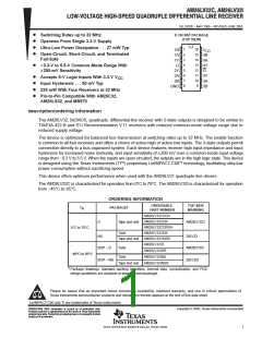
SLLS202E − MAY 1995 − REVISED JUNE 2005
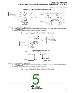
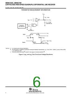
PARAMETER MEASUREMENT INFORMATION
A
B
Generator
(see Note B)
Y
A
B
2 V
1 V
V
O
Input
C
= 15 pF
L
50 Ω
50 Ω
(see Note A)
t
t
PHL
PLH
V
V
OH
90%
90%
V
CC
Output
50%
10%
50%
10%
OL
G
G
t
t
f
r
(see Note C)
NOTES: A.
C includes probe and jig capacitance.
L
B. The input pulse is supplied by a generator having the following characteristics: Z = 50 Ω, PRR = 10 MHz, t and t (10% to 90%)
O
r
f
≤ 2 ns, 50% duty cycle.
C. To test the active-low enable G, ground G and apply an inverted waveform G.
Figure 1. t
and t
Test Circuit and Voltage Waveforms
PLH
PHL
A
B
Y
V
O
V
ID
= 1 V
C
= 15 pF
(see Note A)
L
R
= 2 kΩ
L
G
Generator
(see Note B)
G
50 Ω
V
CC
(see Note C)
V
CC
Input
50%
50%
0 V
t
t
PHZ
PZH
V
OH
V
OH
− 0.3 V
50%
Output
V
off
≈ 0
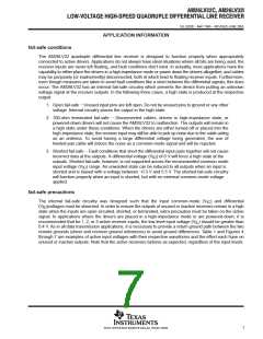
NOTES: A.
C includes probe and jig capacitance.
L
B. The input pulse is supplied by a generator having the following characteristics: Z = 50 Ω, PRR = 10 MHz, t and t (10% to 90%)
O
r
f
≤ 2 ns, 50% duty cycle.
C. To test the active-low enable G, ground G and apply an inverted waveform G.
Figure 2. t
and t
Test Circuit and Voltage Waveforms
PZH
PHZ
5
POST OFFICE BOX 655303 • DALLAS, TEXAS 75265

 TI [ TEXAS INSTRUMENTS ]