ADS1291
ADS1292
ADS1292R
SBAS502A –DECEMBER 2011–REVISED MARCH 2012
www.ti.com
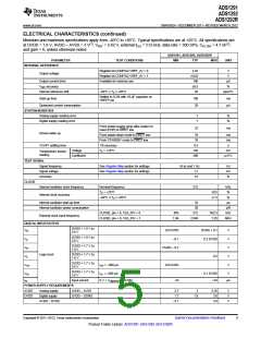
ELECTRICAL CHARACTERISTICS (continued)
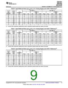
Minimum and maximum specifications apply from –40°C to +85°C. Typical specifications are at +25°C. All specifications are
at DVDD = 1.8 V, AVDD – AVSS = 3 V(1), VREF = 2.42 V, external fCLK = 512 kHz, data rate = 500 SPS, CFILTER = 4.7 nF(2)
,
and gain = 6, unless otherwise noted.
ADS1291, ADS1292, ADS1292R
PARAMETER
TEST CONDITIONS
MIN
TYP
MAX
UNIT
DIGITAL FILTER
–3-dB bandwidth
0.262 fDR
4
Hz
Digital filter settling
RIGHT LEG DRIVE (RLD) AMPLIFIER
RLD integrated noise
Full setting
Conversions
BW = 150 Hz
1.4
100
0.07
–85
μVRMS
kHz
V/μs
dB
GBP
SR
Gain bandwidth product
Slew rate
50 kΩ || 10 pF load, gain = 1
50 kΩ || 10 pF load, gain = 1
fIN = 100 Hz, gain = 1
THD
CMIR
Total harmonic distortion
Common-mode input range
Common-mode resistor matching
Short-circuit current
AVSS + 0.3
AVDD – 0.3
V
Internal 200-kΩ resistor matching
0.1
1.1
5
%
ISC
mA
μA
Quiescent power consumption
LEAD-OFF DETECT
Frequency
See Register Map section for settings
ILEAD_OFF [1:0] = 00
0, fDR/4
6
kHz
nA
nA
μA
μA
%
ILEAD_OFF [1:0] = 01
22
Current
ILEAD_OFF [1:0] = 10
6
ILEAD_OFF [1:0] = 11
22
Current accuracy
Comparator threshold accuracy
RESPIRATION (ADS1292R)
±10
±10
mV
Internal source
32, 64
kHz
kHz
Frequency
External source
32
0
64
168.75
10,000
Phase shift
See Register Map section for settings
IRESP = 30 µA
112.5
2000
Degrees
Ω
Impedance range
0.05-Hz to 2-Hz brick wall filter, 32-kHz
modulation clock, phase = 112.5,
using IRESP = 30 µA with 2-kΩ baseline load,
gain = 4
Impedance measurement noise
Maximum modulator current
40
mΩPP
μA
Using Internal reference
100
EXTERNAL REFERENCE
3-V supply VREF = (VREFP – VREFN)
5-V supply VREF = (VREFP – VREFN)
2
2
2.5
4
VDD – 0.3
VDD – 0.3
V
V
Reference input voltage
VREFN
VREFP
Negative input
Positive input
AVSS
V
AVSS + 2.5
120
V
Input impedance
kΩ
4
Submit Documentation Feedback
Copyright © 2011–2012, Texas Instruments Incorporated
Product Folder Link(s): ADS1291 ADS1292 ADS1292R

 TI [ TEXAS INSTRUMENTS ]