ADS1274
ADS1278
www.ti.com
SBAS367F –JUNE 2007–REVISED FEBRUARY 2011
APPLICATION INFORMATION
5. Reference Inputs: It is recommended to use a
minimum 10μF tantalum with a 0.1μF ceramic
capacitor directly across the reference inputs,
VREFP and VREFN. The reference input should
be driven by a low-impedance source. For best
performance, the reference should have less than
3μVRMS in-band noise. For references with noise
higher than this level, external reference filtering
may be necessary.
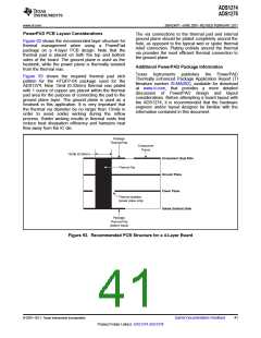
To obtain the specified performance from the
ADS1274/78, the following layout and component
guidelines should be considered.
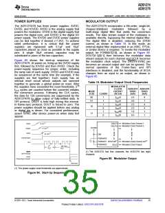
1. Power Supplies: The device requires three
power supplies for operation: DVDD, IOVDD, and
AVDD. The allowed range for DVDD is 1.65V to
1.95V; (for 32.768MHz < fCLK ≤ 37MHz: 2.0V to
2.2V) the range of IOVDD is 1.65V to 3.6V;
AVDD is restricted to 4.75V to 5.25V. For all
6. Analog Inputs: The analog input pins must be
supplies, use
a
10μF tantalum capacitor,
driven differentially to achieve specified
bypassed with a 0.1μF ceramic capacitor, placed
close to the device pins. Alternatively, a single
10μF ceramic capacitor can be used. The
supplies should be relatively free of noise and
should not be shared with devices that produce
voltage spikes (such as relays, LED display
drivers, etc.). If a switching power-supply source
is used, the voltage ripple should be low (less
than 2mV) and the switching frequency outside
the passband of the converter.
performance.
A
true differential driver or
transformer (ac applications) can be used for this
purpose. Route the analog inputs tracks (AINP,
AINN) as a pair from the buffer to the converter
using short, direct tracks and away from digital
tracks. A 1nF to 10nF capacitor should be used
directly across the analog input pins, AINP and
AINN. A low-k dielectric (such as COG or film
type) should be used to maintain low THD.
Capacitors from each analog input to ground can
be used. They should be no larger than 1/10 the
size of the difference capacitor (typically 100pF)
to preserve the ac common-mode performance.
2. Ground Plane: A single ground plane connecting
both AGND and DGND pins can be used. If
separate digital and analog grounds are used,
connect the grounds together at the converter.
7. Component Placement: Place the power supply,
analog input, and reference input bypass
capacitors as close as possible to the device
pins. This layout is particularly important for
small-value ceramic capacitors. Larger (bulk)
decoupling capacitors can be located farther from
the device than the smaller ceramic capacitors.
3. Digital Inputs: It is recommended to
source-terminate the digital inputs to the device
with 50Ω series resistors. The resistors should be
placed close to the driving end of digital source
(oscillator, logic gates, DSP, etc.) This placement
helps to reduce ringing on the digital lines (ringing
may lead to degraded ADC performance).
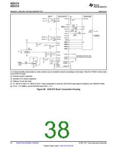
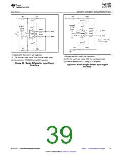
Figure 88 to Figure 90 illustrate basic connections
and interfaces that can be used with the ADS1274.
4. Analog/Digital Circuits: Place analog circuitry
(input buffer, reference) and associated tracks
together, keeping them away from digital circuitry
(DSP, microcontroller, logic). Avoid crossing
digital tracks across analog tracks to reduce
noise coupling and crosstalk.
© 2007–2011, Texas Instruments Incorporated
Submit Documentation Feedback
37
Product Folder Link(s): ADS1274 ADS1278

 TI [ TEXAS INSTRUMENTS ]