71M6521DE/71M6521FE
Energy Meter IC
DATASHEET
JANUARY 2008
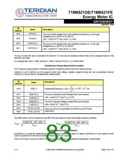
CE Interface Description
CE Program
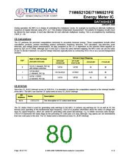
The CE program is supplied by TERIDIAN as a data image that can be merged with the MPU operational code for meter
applications. Typically, the CE program covers most applications and does not need to be modified. For EQU = 0 and EQU =
1, CE code CE21A04_2 should be used. For EQU = 2, CE code image CE21A03_2 should be used. The description in this
section applies to CE code revision CE21A03_2.
Formats
All CE words are 4 bytes. Unless specified otherwise, they are in 32-bit two’s complement (-1 = 0xFFFFFFFF). ‘Calibration’
parameters are defined in flash memory (or external EEPROM) and must be copied to CE data memory by the MPU before
enabling the CE. ‘Internal’ variables are used in internal CE calculations. ‘Input’ variables allow the MPU to control the behavior
of the CE code. ‘Output’ variables are outputs of the CE calculations. The corresponding MPU address for the most significant
byte is given by 0x1000 + 4 x CE_address and 0x1003 + 4 x CE_address for the least significant byte.
Constants
Constants used in the CE Data Memory tables are:
ꢀ
ꢀ
ꢀ
ꢀ
ꢀ
ꢀ
FS = 32768Hz/13 = 2520.62Hz.
F0 is the fundamental frequency.
IMAX is the external rms current corresponding to 250mV pk at the inputs IA and IB.
VMAX is the external rms voltage corresponding to 250mV pk at the VA and VB inputs.
NACC, the accumulation count for energy measurements is PRE_SAMPS*SUM_CYCLES.
Accumulation count time for energy measurements is PRE_SAMPS*SUM_CYCLES/FS.
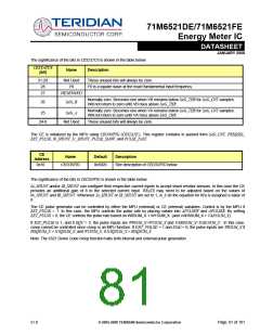
The system constants IMAX and VMAX are used by the MPU to convert internal quantities (as used by the CE) to external, i.e.
metering quantities. Their values are determined by the off-chip scaling of the voltage and current sensors used in an actual
meter. The LSB values used in this document relate digital quantities at the CE or MPU interface to external meter input
quantities. For example, if a SAG threshold of 80V peak is desired at the meter input, the digital value that should be pro-
grammed into SAG_THR would be 80V/SAG_THRLSB, where SAG_THRLSB is the LSB value in the description of SAG_THR.
The parameters EQU, CE_E, PRE_SAMPS, and SUM_CYCLES essential to the function of the CE are stored in I/O RAM (see I/O
RAM section).
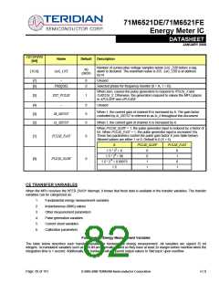
Environment
Before starting the CE using the CE_E bit, the MPU has to establish the proper environment for the CE by implementing the
following steps:
ꢀ
ꢀ
ꢀ
ꢀ
ꢀ
ꢀ
Load the CE data into CE DRAM.
Establish the equation to be applied in EQU.
Establish the accumulation period and number of samples in PRE_SAMPS and SUM_CYCLES.
Establish the number of cycles per ADC mux frame.
Set PLS_INTERVAL[7:0] to 81.
Set FIR_LEN to 1 and MUX_DIV to 1.
There must be thirteen 32768Hz cycles per ADC mux frame (see System Timing Diagram, Figure 16). This means that the
product of the number of cycles per frame and the number of conversions per frame must be 12 (allowing for one settling
cycle). The required configuration is FIR_LEN = 1 (three cycles per conversion) and MUX_DIV = 1 (4 conversions per mux
frame).
v1.0
© 2005-2008 TERIDIAN Semiconductor Corporation
Page: 79 of 101

 TERIDIAN [ TERIDIAN SEMICONDUCTOR CORPORATION ]