71M6521DE/71M6521FE
Energy Meter IC
DATASHEET
JANUARY 2008
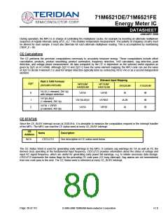
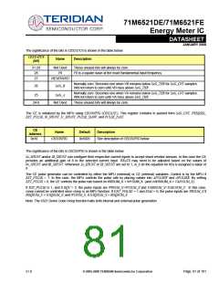
The significance of the bits in CESTATUS is shown in the table below:
CESTATUS
Name
Description
[bit]
31-29
28
Not Used
F0
These unused bits will always be zero.
F0 is a square wave at the exact fundamental input frequency.
27
RESERVED
Normally zero. Becomes one when VB remains below SAG_THR for SAG_CNT samples.
Will not return to zero until VB rises above SAG_THR.
26
SAG_B
Normally zero. Becomes one when VA remains below SAG_THR for SAG_CNT samples.
Will not return to zero until VA rises above SAG_THR.
25
SAG_A
24-0
Not Used
These unused bits will always be zero.
The CE is initialized by the MPU using CECONFIG (CESTATE.). This register contains in packed form SAG_CNT, FREQSEL,
EXT_PULSE, I0_SHUNT, I1_SHUNT, PULSE_SLOW, and PULSE_FAST.
CE
Address
Name
Default
Description
0x10
CECONFIG
0x5020
See description of CECONFIG below
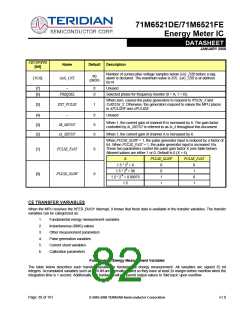
The significance of the bits in CECONFIG is shown in the table below:
IA_SHUNT and/or IB_SHUNT can configure their respective current inputs to accept shunt resistor sensors. In this case the CE
provides an additional gain of 8 to the selected current input. WRATE may need to be adjusted based on the values of
IA_SHUNT and IB_SHUNT. Whenever IA_SHUNT or IB_SHUNT are set to 1, In_8 (in the equation for Kh) is assigned a value of
8.
The CE pulse generator can be controlled by either the MPU (external) or CE (internal) variables. Control is by the MPU if
EXT_PULSE = 1. In this case, the MPU controls the pulse rate by placing values into APULSEW and APULSER. By setting
EXT_PULSE = 0, the CE controls the pulse rate based on W0SUM_X + W1SUM_X (and VAR0SUM_X + VAR1SUM_X).
If EXT_PULSE is 1, and if EQU = 2, the pulse inputs are W0SUM_X+W1SUM_X and VAR0SUM_X+VAR1SUM_X . In this case,
creep cannot be controlled since creep is an MPU function. If EXT_PULSE = 1 and EQU = 0, the pulse inputs are W0SUM_X if
I0SQSUM_X > I1SQSUM_X, and W1SUM_X, if I1SQSUM_X > I0SQSUM_X.
Note: The 6521 Demo Code creep function halts both internal and external pulse generation.
v1.0
© 2005-2008 TERIDIAN Semiconductor Corporation
Page: 81 of 101

 TERIDIAN [ TERIDIAN SEMICONDUCTOR CORPORATION ]