71M6521DE/71M6521FE
Energy Meter IC
DATASHEET
JANUARY 2008
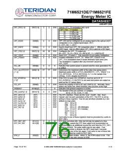
OPT_FDC[1:0]
OPT_RXDIS
2007[1:0]
2008[5]
0
0
0
0
R/W Selects OPT_TX modulation duty cycle
OPT_FDC
Function
00
01
10
11
50% Low
25% Low
12.5% Low
6.25% Low
R/W OPT_RX can be configured as an analog input to the optical UART
comparator or as a digital input/output, DIO1.
0—OPT_RX, 1—DIO1.
OPT_RXINV
2008[4]
0
0
R/W Inverts result from OPT_RX comparator when 1. Affects only the
UART input. Has no effect when OPT_RX is used as a DIO input.
R/W Configures the OPT_TX output pin.
OPT_TXE[1,0]
2007[7,6]
00
00
00—OPT_TX, 01—DIO2, 10—WPULSE, 11—VARPULSE
R/W Invert OPT_TX when 1. This inversion occurs before modulation.
R/W Enables modulation of OPT_TX. When OPT_TXMOD is set,
OPT_TX is modulated when it would otherwise have been zero.
The modulation is applied after any inversion caused by
OPT_TXINV.
OPT_TXINV
OPT_TXMOD
2008[0]
2008[1]
0
0
0
0
PLL_OK
2003[6]
0
0
R
Indicates that system power is present and the clock generation PLL
is settled.
PLS_MAXWIDTH
[7:0]
2080[7:0]
FF
FF
R/W Determines the maximum width of the pulse (low going pulse).
Maximum pulse width is (2*PLS_MAXWIDTH + 1)*TI. Where TI is
PLS_INTERVAL. If PLS_INTERVAL=0, TI is the sample time
(397µs). If 255, disable MAXWIDTH.
PLS_INTERVAL
[7:0]
2081[7:0]
2004[6]
0
0
0
0
R/W If the FIFO is used, PLS_INTERVAL must be set to 81. If
PLS_INTERVAL = 0, the FIFO is not used and pulses are output as
soon as the CE issues them.
R/W Inverts the polarity of WPULSE and VARPULSE. Normally, these
pulses are active low. When inverted, they become active high.
PLS_INV
PREBOOT
SFRB2[7]
2001[7:6]
--
0
--
0
R
Indicates that preboot sequence is active.
The duration of the pre-summer, in samples.
00-42, 01-50, 10-84, 11-100.
PRE_SAMPS[1:0]
R/W
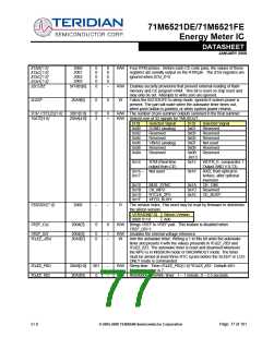
RTC_SEC[5:0]
RTC_MIN[5:0]
RTC_HR[4:0]
RTC_DAY[2:0]
RTC_DATE[4:0]
RTC_MO[3:0]
RTC_YR[7:0]
2015
2016
2017
2018
2019
201A
201B
--
--
--
--
--
--
--
--
--
--
--
--
--
--
R/W The RTC interface. These are the ‘year’, ‘month’, ‘day’, ‘hour’,
R/W ‘minute’ and ‘second’ parameters of the RTC. The RTC is set by
R/W writing to these registers. Year 00 and all others divisible by 4 are
R/W defined as leap years.
R/W
R/W
R/W
SEC 00 to 59
MIN 00 to 59
HR
00 to 23 (00=Midnight)
DAY 01 to 07 (01=Sunday)
DATE 01 to 31
MO 01 to 12
YR
00 to 99
Each write to one of these registers must be preceded by a write to
201F (WE).
RTC_DEC_SEC
RTC_INC_SEC
201C[1]
201C[0]
0
0
0
0
W
RTC time correction bits. Only one bit may be pulsed at a time.
When pulsed, causes the RTC time value to be incremented (or
decremented) by an additional second the next time the RTC_SEC
register is clocked. The pulse width may be any value. If an
additional correction is desired, the MPU must wait 2 seconds
before pulsing one of the bits again. Each write to one of these bits
must be preceded by a write to 201F (WE).
RTM_E
2002[3]
0
0
R/W Real Time Monitor enable. When ‘0’, the RTM output is low. This
bit enables the two wire version of RTM
Page: 76 of 101
© 2005-2008 TERIDIAN Semiconductor Corporation
v1.0

 TERIDIAN [ TERIDIAN SEMICONDUCTOR CORPORATION ]