71M6521BE
Energy Meter IC
DATA SHEET
JANUARY 2008
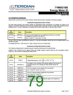
Pulse Generation
Description
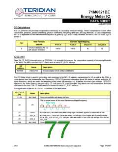
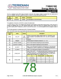
CE
Address
Name
Default
Kh = VMAX*IMAX*47.1132 / (In_8*WRATE*NACC*X) Wh/pulse. The default
value results in a Kh of 1.0Wh/pulse when 2520 samples are taken in each
accumulation interval (and VMAX=600, IMAX = 208, In_8 = 1, X = 6).
0x1044
WRATE
389
The maximum value for WRATE is 215 – 1.
WRATE controls the number of pulses that are generated per measured Wh quantities. The lower WRATE is the slower the
pulse rate for measured energy quantity. The metering constant Kh is derived from WRATE as the amount of energy measured
for each pulse. That is, if Kh = 1Wh/pulse, a power applied to the meter of 120V and 30A results in one pulse per second. If
the load is 240V at 150A, ten pulses per second will be generated. X is controlled by the PULSE_FAST and PULSE_SLOW bits
in the CECONFIG register.
The maximum pulse rate is 7.5kHz. The maximum time jitter is 67µs and is independent of the number of pulses measured.
Thus, if the pulse generator is monitored for 1 second, the peak jitter is 67ppm. After 10 seconds, the peak jitter is 6.7ppm.
The average jitter is always zero. If it is attempted to drive either pulse generator faster than its maximum rate, it will simply
output at its maximum rate without exhibiting any rollover characteristics. The actual pulse rate, using WSUM as an example,
is:
WRATE ⋅WSUM ⋅ FS ⋅ X
,
RATE =
Hz
246
where FS = sampling frequency (2520.6Hz), X = Pulse speed factor
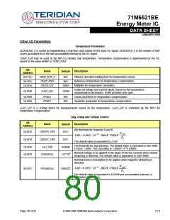
CE Calibration Parameters
The table below lists the parameters that are typically entered to effect calibration of meter accuracy.
CE
Name
Default
Description
Address
0x1020
0x1024
0x1028
0x102C
CAL_IA
CAL_VA
CAL_IB
CAL_VB
16384
16384
16384
16384
These constants control the gain of their respective channels. The nominal
value for each parameter is 214 = 16384. The gain of each channel is directly
proportional to its CAL parameter. Thus, if the gain of a channel is 1% slow,
CAL should be scaled by 1/(1 – 0.01).
These two constants control the CT phase compensation. No compensation
occurs when PHADJ_X = 0. As PHADJ_X is increased, more compensation
(lag) is introduced. Range: ±215 – 1. If it is desired to delay the current by the
angle Φ:
0x1030
0x1034
PHADJ_A
PHADJ_B
0
0
0.02229 ⋅TANΦ
0.1487 − 0.0131⋅TANΦ
0.0155⋅TANΦ
PHADJ _ X = 220
at 60Hz
PHADJ _ X = 220
at 50Hz
0.1241− 0.009695⋅TANΦ
V1.0
© 2005-2008 TERIDIAN Semiconductor Corporation
Page: 81 of 97

 TERIDIAN [ TERIDIAN SEMICONDUCTOR CORPORATION ]