U6083B
Parameters
Test Conditions / Pins
Symbol
Min.
Typ.
Max.
Unit
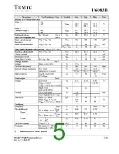
Battery overvoltage detection
Stage 1:
– on
– off
V
V
18.3
16.7
20.0
18.5
21.7
20.3
V
Batt
Batt
Stage 2:
Detection stage 2
– on
– off
I = 30 mA
S
25.5
19.5
18.5
28.5
23.0
20.0
32.5
26.5
21.5
V
V
Stabilized voltage
Short-circuit protection
Pin 1
Pin 6
V
s
Short-circuit current
limitation
Short-circuit detection
V
T1
V
T2
= V – V
V
85
100
120
mV
mV
S
6
T1
= V – V
V
T2
75
3
90
10
105
30
S
6
V
– V
T2
T1
Delay timer short circuit detection, V
= 12 V Pin 5
Batt
Switched off threshold
Charge current
Discharge current
Capacitance current
Voltage doubler
Voltage
V
= V – V
V
10.2
5
10.4
13
3
10.6
15
V
A
A
T5
S
5
T5
I
ch
I
dis
I = I – I
5
I
5
10
mA
ch
dis
Pin 7
Duty cycle 100%
V
f
V
2 V
S
280
26
7
7
Oscillator frequency
Internal voltage limitation
400
27.5
520
30.0
kHz
V
7
I = 5 mA
7
(whichever is lower)
V
S+14
V
S+15
V
S+16
Edge steepness
dv /dt = dV /dt
53
63
72
130
V/ms
V
8
4
4
4
dV /dt
8
max
Gate output
Voltage
Pin 8
Low level
= 16.5 V
V
8
0.35
0.70
0.95
1.5 *)
V
Batt
T
amb
= 110°C, R = 150
3
High level,
V
8
V
7
duty cycle 100%
Current
V = Low level
I
1.0
–1.0
15
100
65
mA
%
8
8
V = High level, I > | I |
8
7
8
Duty cycle
Min: C = 68 nF
t /T
p
18
73
21
81
2
Max: V
12.4 V
Batt
V
Batt
= 16.5 V, C = 68 nF
2
Oscillator
Frequency
Threshold cycle
Pin4
f
10
0.68
2000
0.72
Hz
0.7
VT100
VS
1
V8
V8
High,
1
Upper
Lower
0.65
0.26
0.67
0.28
0.69
0.3
VT
2
3
100
Low,
2
VS
VTL
VS
3
Oscillator current
Frequency
V
= 12 V
I
f
34
56
45
75
54
90
A
Hz
Batt
osc
C open, C = 68 nF
4
2
duty cycle = 50%
*)
Reference point is battery ground.
TELEFUNKEN Semiconductors
5 (8)
Rev. A1, 14-Feb-97

 TEMIC [ TEMIC SEMICONDUCTORS ]