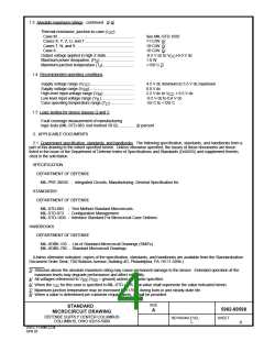
1.3 Absolute maximum ratings - continued. 3/ 4/
):
JC
Thermal resistance, junction-to-case (
Case M.......................................................................
Cases X, Y, Z, U, and 7 .............................................
Cases T, N, and 9......................................................
Case 8........................................................................
Output voltage applied in high Z state .........................
See MIL-STD-1835
11 C/W 6/
10 C/W 6/
16 C/W 6/
-0.5 V dc to V +0.5 V dc
CC
Maximum power dissipation, (P ) ...............................
Maximum junction temperature (T ) ............................
J
1.0 W
D
+150 C 7/
1.4 Recommended operating conditions.
Supply voltage range (V ) ........................................
CC
4.5 V dc minimum to 5.5 V dc maximum
0.0 V dc
Supply voltage range (V ).........................................
SS
High level input voltage range (V ) ............................
IH
2.2 V dc to V
+ 0.5 V dc
CC
Low level input voltage range (V )..............................
-0.5 V dc to 0.8 V dc
-55 C to +125 C
IL
Case operating temperature range (T )......................
C
1.5 Logic testing for device classes Q and V.
Fault coverage measurement of manufacturing
logic tests (MIL-STD-883, test method 5012) .............. 8/ percent
2. APPLICABLE DOCUMENTS
2.1 Government specification, standards, and handbooks. The following specification, standards, and handbooks form a
part of this drawing to the extent specified herein. Unless otherwise specified, the issues of these documents are those
listed in the issue of the Department of Defense Index of Specifications and Standards (DoDISS) and supplement thereto,
cited in the solicitation.
SPECIFICATION
DEPARTMENT OF DEFENSE
MIL-PRF-38535 - Integrated Circuits, Manufacturing, General Specification for.
STANDARDS
DEPARTMENT OF DEFENSE
MIL-STD-883 - Test Method Standard Microcircuits.
MIL-STD-973 - Configuration Management.
MIL-STD-1835 - Interface Standard For Microcircuit Case Outlines.
HANDBOOKS
DEPARTMENT OF DEFENSE
MIL-HDBK-103 - List of Standard Microcircuit Drawings (SMD's).
MIL-HDBK-780 - Standard Microcircuit Drawings.
(Unless otherwise indicated, copies of the specification, standards, and handbooks are available from the Standardization
Document Order Desk, 700 Robbins Avenue, Building 4D, Philadelphia, PA 19111-5094.)
3/ Stresses above the absolute maximum rating may cause permanent damage to the device. Extended operation at the
maximum levels may degrade performance and affect reliability.
4/ All voltages referenced to V
(V
SS SS
= ground) unless otherwise specified.
6/ When the
for this case is specified in MIL-STD-1835, that value shall supersede the value indicated herein.
JC
7/ Maximum junction temperature may be increased to +175 C during burn-in and steady-state life.
8/ When a value is determined per customer requirements, it shall be provided.
SIZE
STANDARD
MICROCIRCUIT DRAWING
5962-89598
A
DEFENSE SUPPLY CENTER COLUMBUS
COLUMBUS, OHIO 43216-5000
REVISION LEVEL
L
SHEET
4
DSCC FORM 2234
APR 97

 TEMIC [ TEMIC SEMICONDUCTORS ]