AN1009
Application Notes
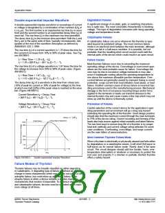
Characteristics Formulas for Phase Control Circuits
Max. Load
Max. Average Thyristor
or Rectifier Current
PRV
Voltage
E =Avg.
d
Circuit
Name
Half-wave
Resistive
Load
Max Thyristor
Voltage
Load Voltage
E =RMS
SCR
EP
with Delayed Firing
Avg. Amps
Cond. Period
a
1.4 ERMS
180
E
π
E
E
P
P
P
E
E
= -------
E
= ------- (1 + cosα)
2π
-------
d
a
d
πR
E
E
1
P
P
π
ꢀ
.
= -------
E
E
= ---------- π – α + -- sin2α
a
a
0
2
2
2
Full-wave
Bridge
1.4 ERMS
1.4 ERMS
EP
EP
180
180
2E
π
E
E
πR
P
P
π
P
E
= ----------
E
= ----------(1 + cosα)
-------
d
d
2
Full-wave
AC Switch
Resistive
Load
E
P
E
E
1
P
P
ꢀ
.
E
= -------
= ---------- π – α + -- sin2α
-------
a
0
1.4
2
πR
2π
NOTE: Angle alpha (α) is in radians.
EP
0
R
Load
E
RMS
α
Half-wave Resistive Load – Schematic
Half-wave Resistive Load – Waveform
L
EP
Load
0
E
R
α
Full-wave Bridge – Schematic
Full-wave Bridge – Waveform
EP
0
R
Load
E
RMS
α
Full-wave AC Switch Resistive Load – Schematic
Full-wave AC Switch Resistive Load – Waveform
http://www.teccor.com
+1 972-580-7777
AN1009 - 4
©2002 Teccor Electronics
Thyristor Product Catalog

 TECCOR [ TECCOR ELECTRONICS ]