Application Notes
AN1009
Degradation Failures
Double-exponential Impulse Waveform
A significant change of on-state, gate, or switching characteris-
tics is quite rare. The most vulnerable characteristic is blocking
voltage. This type of degradation increases with rising operating
voltage and temperature levels.
A double-exponential impulse waveform or waveshape of current
or voltage is designated by a combination of two numbers (tr/td or
tr x td µs). The first number is an exponential rise time (tr) or wave
front and the second number is an exponential decay time (td) or
wave tail. The rise time (tr) is the maximum rise time permitted.
The decay time (td) is the minimum time permitted. Both the tr and
the td are in the same units of time, typically microseconds, des-
ignated at the end of the waveform description as defined by
ANSI/IEEE C62.1-1989.
Catastrophic Failures
A catastrophic failure can occur whenever the thyristor is oper-
ated beyond its published ratings. The most common failure
mode is an electrical short between the main terminals, although
a triac can fail in a half-wave condition. It is possible, but not
probable, that the resulting short-circuit current could melt the
internal parts of the device which could result in an open circuit.
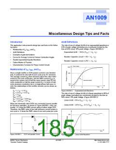
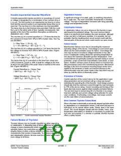
The rise time (tr) of a current waveform is 1.25 times the time for
the current to increase from 10% to 90% of peak value. See Fig-
ure AN1009.5.
tr = Rise Time = 1.25 • [tc – ta]
tr = 1.25 • [t(0.9 IPK) – t(0.1 IPK)] = T1 – T0
Failure Causes
Most thyristor failures occur due to exceeding the maximum
operating ratings of the device. Overvoltage or overcurrent oper-
ations are the most probable cause for failure. Overvoltage fail-
ures may be due to excessive voltage transients or may also
occur if inadequate cooling allows the operating temperature to
rise above the maximum allowable junction temperature. Over-
current failures are generally caused by improper fusing or circuit
protection, surge current from load initiation, load abuse, or load
failure. Another common cause of device failure is incorrect han-
dling procedures used in the manufacturing process. Mechanical
damage in the form of excessive mounting torque and/or force
applied to the terminals or leads can transmit stresses to the
internal thyristor chip and cause cracks in the chip which may not
show up until the device is thermally cycled.
The rise time (tr) of a voltage waveform is 1.67 times the time for
the voltage to increase from 30% to 90% of peak value. (Figure
AN1009.5)
t = Rise Time = 1.67 • [tc – t ]
t = 1.67 • [t(0.9 VPK) – t(0.3bVPK)] = T1 – T0
r
r
The decay time (td) of a waveform is the time from virtual zero
(10% of peak for current or 30% of peak for voltage) to the time
at which one-half (50%) of the peak value is reached on the wave
tail. (Figure AN1009.5)
Current Waveform td = Decay Time
= [t(0.5 IPK) – t(0.1 IPK)] = T2 – T0
Voltage Waveform td = Decay Time
= [t(0.5 VPK) – t(0.3 VPK)] = T2 – T0
Prevention of Failures
Careful selection of the correct device for the application’s oper-
ating parameters and environment will go a long way toward
extending the operating life of the thyristor. Good design practice
should also limit the maximum current through the main terminals
to 75% of the device rating. Correct mounting and forming of the
leads also help ensure against infant mortality and latent failures.
The two best ways to ensure long life of a thyristor is by proper
heat sink methods and correct voltage rating selection for worst
case conditions. Overheating, overvoltage, and surge currents
are the main killers of semiconductors.
t
-
Decay = e
Virtual Start of Wavefront
1.44 T
2
(Peak Value)
100%
90%
50%
30%
Most Common Thyristor Failure Mode
When a thyristor is electrically or physically abused and fails either
by degradation or a catastrophic means, it will short (full-wave or
half-wave) as its normal failure mode. Rarely does it fail open
circuit. The circuit designer should add line breaks, fuses, over-
temperature interrupters or whatever is necessary to protect the
end user and property if a shorted or partially shorted thyristor
offers a safety hazard.
10%
0%
T
t
t
t
T
T
2
0
a
b
c
1
Time
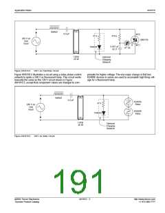
Figure AN1009.5
Double-exponential Impulse Waveform
Failure Modes of Thyristor
Thyristor failures may be broadly classified as either degrading
or catastrophic. A degrading type of failure is defined as a
change in some characteristic which may or may not cause a cat-
astrophic failure, but could show up as a latent failure. Cata-
strophic failure is when a device exhibits a sudden change in
characteristic that renders it inoperable. To minimize degrading
and catastrophic failures, devices must be operated within maxi-
mum ratings at all times.
©2002 Teccor Electronics
Thyristor Product Catalog
AN1009 - 3
http://www.teccor.com
+1 972-580-7777

 TECCOR [ TECCOR ELECTRONICS ]