Battrax SLIC Protector
Battrax SLIC Protector
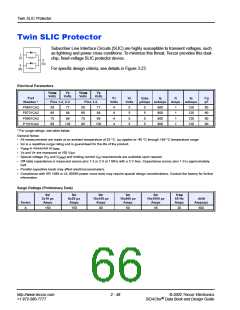
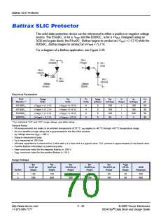
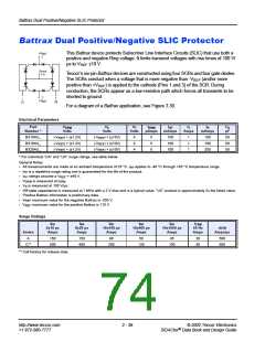
This solid state protection device can be referenced to either a positive or negative voltage
source. The B1xx0C_ is for a -VREF and the B2050C_ is for a +VREF. Designed using an
SCR and a gate diode, the B1xx0C_ Battrax begins to conduct at |-VREF| + |-1.2 V| while the
B2050C_ Battrax begins to conduct at |+VREF| + |1.2 V|.
For a diagram of a Battrax application, see Figure 3.29.
Pin 3
(+V
Pin 2
(Ground)
)
Pin 1
REF
(Line)
Pin 3
(-V
)
REF
Gate
Pin 1
Pin 2
(Ground)
(Line)
-Battrax
B1xx0C_
+Battrax
B2050C_
Electrical Parameters
Part
VDRM
Volts
VS
VT
IDRM
IGT
IT
IH
CO
pF
Number *
Volts
Volts
µAmps
mAmps
Amps
mAmps
B1100C_
B1160C_
B1200C_
B2050C_
|-VREF| + |-1.2 V|
|-VREF| + |-1.2 V|
|-VREF| + |-1.2 V|
|+VREF| + |1.2 V|
|-VREF| + |-10 V|
|-VREF| + |-10 V|
|-VREF| + |-10 V|
|+VREF| + |10 V|
4
4
4
4
5
5
5
5
100
100
100
50
1
1
1
1
100
160
200
5
50
50
50
50
* For individual “CA” and “CC” surge ratings, see table below.
General Notes:
•
•
•
•
•
•
•
•
•
All measurements are made at an ambient temperature of 25 °C. IPP applies to -40 °C through +85 °C temperature range.
I
PP is a repetitive surge rating and is guaranteed for the life of the product.
PP ratings assume VREF = ±48 V.
I
V
DRM is measured at IDRM.
VS is measured at 100 V/µs.
Off-state capacitance is measured at 1 MHz with a 2 V bias and is a typical value. “CC” product is approximately 2x the listed value.
Positive Battrax information is preliminary data.
V
V
REF maximum value for the negative Battrax is -200 V.
REF maximum value for the positive Battrax is 110 V.
Surge Ratings
IPP
IPP
IPP
IPP
IPP
ITSM
60 Hz
Amps
2x10 µs
Amps
8x20 µs
Amps
10x160 µs
Amps
10x560 µs
Amps
10x1000 µs
Amps
di/dt
Series
Amps/µs
A
C
150
500
150
400
90
200
60
150
50
100
40
50
500
500
http://www.teccor.com
+1 972-580-7777
2 - 52
© 2002 Teccor Electronics
®
SIDACtor Data Book and Design Guide

 TECCOR [ TECCOR ELECTRONICS ]