Twin SLIC Protector
Twin SLIC Protector
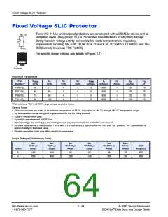
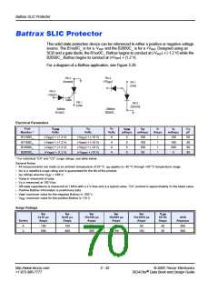
Subscriber Line Interface Circuits (SLIC) are highly susceptible to transient voltages, such
as lightning and power cross conditions. To minimize this threat, Teccor provides this dual-
chip, fixed-voltage SLIC protector device.
1
(T)
2
(G)
3
For specific design criteria, see details in Figure 3.23.
(R)
Electrical Parameters
VDRM
VS
VDRM
Volts
VS
Volts
Volts
Volts
Part
VT
VF
IDRM
IS
IT
IH
CO
pF
Number *
Pins 1-2, 2-3
Pins 1-3
Volts
Volts
µAmps mAmps Amps mAmps
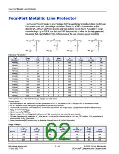
P0641CA2
P0721CA2
P0901CA2
P1101CA2
58
65
75
95
77
88
98
58
65
75
95
77
88
98
4
4
4
4
5
5
5
5
5
5
5
5
800
800
800
800
1
1
1
1
120
120
120
120
60
60
60
60
130
130
* For surge ratings, see table below.
General Notes:
•
•
•
•
•
•
All measurements are made at an ambient temperature of 25 °C. IPP applies to -40 °C through +85 °C temperature range.
I
PP is a repetitive surge rating and is guaranteed for the life of the product.
V
DRM is measured at IDRM.
VS and VF are measured at 100 V/µs.
Special voltage (VS and VDRM) and holding current (IH) requirements are available upon request.
Off-state capacitance is measured across pins 1-2 or 2-3 at 1 MHz with a 2 V bias. Capacitance across pins 1-3 is approximately
half.
•
•
Parallel capacitive loads may affect electrical parameters.
Compliance with GR 1089 or UL 60950 power cross tests may require special design considerations. Contact the factory for further
information.
Surge Ratings (Preliminary Data)
IPP
IPP
IPP
IPP
IPP
ITSM
60 Hz
Amps
2x10 µs
Amps
8x20 µs
Amps
10x160 µs
Amps
10x560 µs
Amps
10x1000 µs
Amps
di/dt
Series
Amps/µs
A
150
150
90
50
45
20
500
http://www.teccor.com
+1 972-580-7777
2 - 48
© 2002 Teccor Electronics
®
SIDACtor Data Book and Design Guide

 TECCOR [ TECCOR ELECTRONICS ]