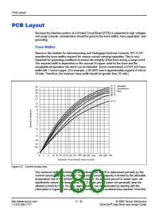
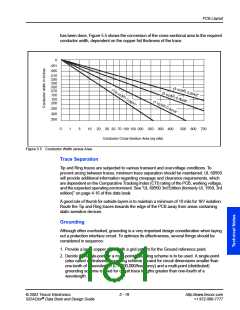
SIDACtor Soldering Recommendations
SIDACtor Soldering Recommendations
When placing surface mount components, a good solder bond is critical because:
•
The solder provides a thermal path in which heat is dissipated from the packaged silicon
to the rest of the board.
•
A good bond is less subject to thermal fatiguing and results in improved component
reliability.
Reflow Soldering
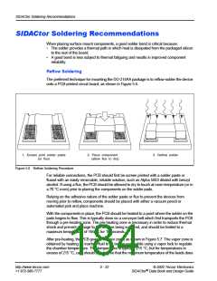
The preferred technique for mounting the DO-214AA package is to reflow-solder the device
onto a PCB-printed circuit board, as shown in Figure 5.6.
1. Screen print solder paste
(or flux)
2. Place component
(allow flux to dry)
3. Reflow solder
Figure 5.6 Reflow Soldering Procedure
For reliable connections, the PCB should first be screen printed with a solder paste or
fluxed with an easily removable, reliable solution, such as Alpha 5003 diluted with benzyl
alcohol. If using a flux, the PCB should be allowed to dry to touch at room temperature (or in
a 70 °C oven) prior to placing the components on the solder pads.
Relying on the adhesive nature of the solder paste or flux to prevent the devices from
moving prior to reflow, components should be placed with either a vacuum pencil or
automated pick and place machine.
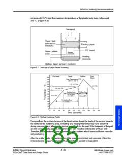
With the components in place, the PCB should be heated to a point where the solder on the
pads begins to flow. This is typically done on a conveyor belt which first transports the PCB
through a pre-heating zone. The pre-heating zone is necessary in order to reduce thermal
shock and prevent damage to the devices being soldered, and should be limited to a
maximum temperature of 165 °C for 10 seconds.
After pre-heating, the PCB goes to a vapor zone, as shown in Figure 5.7. The vapor zone is
obtained by heating an inactive fluid to its boiling point while using a vapor lock to regulate
the chamber temperature. This temperature is typically 215 °C, but for temperatures in
excess of 215 °C, care should be taken so that the maximum temperature of the leads does
http://www.teccor.com
+1 972-580-7777
5 - 22
© 2002 Teccor Electronics
SIDACtor Data Book and Design Guide
®

 TECCOR [ TECCOR ELECTRONICS ]