PCB Layout
PCB Layout
Because the interface portion of a Printed Circuit Board (PCB) is subjected to high voltages
and surge currents, consideration should be given to the trace widths, trace separation, and
grounding.
Trace Widths
Based on the Institute for Interconnecting and Packaging Electronic Currents, IPC D 275
specifies the trace widths required for various current-carrying capacities. This is very
important for grounding conditions to ensure the integrity of the trace during a surge event.
The required width is dependent on the amount of copper used for the trace and the
acceptable temperature rise which can be tolerated. Teccor recommends a 0.025 inch trace
width with 1 ounce copper. (For example, a 38-AWG wire is approximately equal to 8 mils to
10 mils. Therefore, the minimum trace width should be greater than 10 mils.)
Allowable
75 ˚C
60 ˚C Temperature
45 ˚C
30 ˚C
20 ˚C
35
30
25
Rise
20
15
10 ˚C
12
10
8
7
6
5
4
3
2
1.5
1
.75
.50
.25
.125
0
30
200
250 300
0
10 20
600 700
500
1
5
50
150
70 100
400
Conductor Cross-Section Area (sq mils)
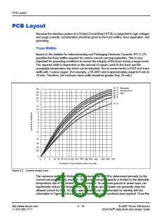
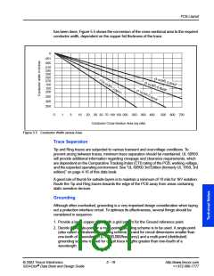
Figure 5.4 Current versus Area
The minimum width and thickness of conductors on a PCB is determined primarily by the
current-carrying capacity required. This current-carrying capacity is limited by the allowable
temperature rise of the etched copper conductor. An adjacent ground or power layer can
significantly reduce this temperature rise. A single ground plane can generally raise the
allowed current by 50%. An easy approximation can be generated by starting with the
information in Figure 5.4 to calculate the conductor cross-sectional area required. Once this
http://www.teccor.com
+1 972-580-7777
5 - 18
© 2002 Teccor Electronics
SIDACtor Data Book and Design Guide
®

 TECCOR [ TECCOR ELECTRONICS ]