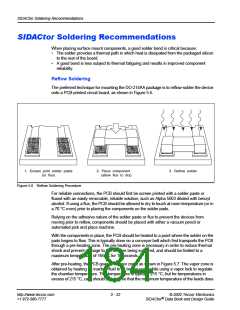
SIDACtor Soldering Recommendations
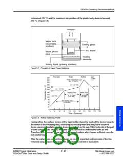
not exceed 275 °C and the maximum temperature of the plastic body does not exceed
250 °C. (Figure 5.8)
Transport
Vapor lock
(secondary
medium)
Cooling pipes
PC board
Vapor phase
zone
Heating
elements
Boiling liquid (primary medium)
Figure 5.7 Principle of Vapor Phase Soldering
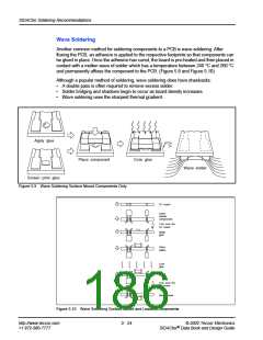
Pre-heat
Soak
Reflow
Cool
Down
260
240
220
Peak Temperature
220 C - 245
C
˚
˚
200
180
160
140
120
100
80
1.3 - 1.6 C/s
˚
<2.5 C/s
˚
0.5 - 0.6 C/s
˚
Soaking Zone
Reflow Zone
60 - 90 s typical
( 2 min. MAX )
30 - 60 s typical
( 2 min. MAX )
<2.5 C/s
˚
Pre-heating Zone
( 2-4 min MAX )
60
40
20
0
0
30
60
90
120
150
180
210
240
270
300
Time (Seconds)
Figure 5.8 Reflow Soldering Profile
During reflow, the surface tension of the liquid solder draws the leads of the device towards
the center of the soldering area, correcting any misalignment that may have occurred
during placement and allowing the device to set flush on the pad. If the footprints of the pad
are not concentrically aligned, the same effect can result in undesirable shifts as well.
Therefore, it is important to use a standard contact pattern which leaves sufficient room for
self-positioning.
After the solder cools, connections should be visually inspected and remnants of the flux
removed using a vapor degreaser with an azeotrope solvent or equivalent.
© 2002 Teccor Electronics
5 - 23
http://www.teccor.com
+1 972-580-7777
®
SIDACtor Data Book and Design Guide

 TECCOR [ TECCOR ELECTRONICS ]