UL 497
Performance Tests
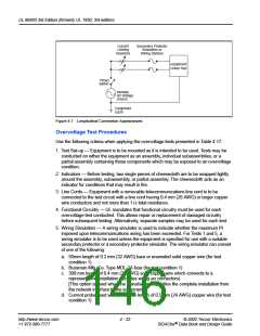
Key performance tests which concern overvoltage protectors are detailed in the arrestor
test section. Specific requirements are:
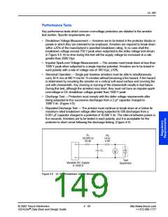
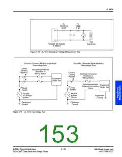
•
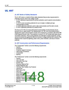
Breakdown Voltage Measurement — Arrestors are to be tested in the protector blocks or
panels in which they are intended to be employed. Arrestors are required to break down
within ±25% of the manufacturer’s specified breakdown rating. In no case shall the
breakdown voltage exceed 750 V peak when subjected to the strike voltage test shown
in Figure 4.8. At no time during this test will the supply voltage be increased at a rate
greater than 2000 V/µs.
•
•
Impulse Spark-over Voltage Measurement — The arrestor must break down at less than
1000 V peak when subjected to a single impulse potential. Arrestors are to be tested in
each polarity with a rate of voltage rise of 100 V/µs, ±10%.
Abnormal Operation — Single pair fuseless arrestors must be able to simultaneously
carry 30 A rms at 480 V rms for 15 minutes without becoming a fire hazard. A fire hazard
is determined by mounting the arrestor on a vertical soft wood surface and covering the
unit with cheesecloth. Any charring or burning of the cheesecloth results in test failure.
During this test, although the arrestors may short, they must not have an impulse spark-
overvoltage or DC breakdown voltage greater than 1500 V peak.
•
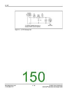
•
Discharge Test — Protectors must comply with the strike voltage requirements after
being subjected to five successive discharges from a 2 µF capacitor charged to
1000 V dc. (Figure 4.9).
Repeated Discharge Test — The arrestor must continue to break down at or below its
maximum rated breakdown voltage after being subjected to 500 discharges from a
0.001 µF capacitor charged to a potential of 10,000 V dc. The interval between pulses is
five seconds. Arrestors are to be tested in each polarity, and it is acceptable for the
protector to short circuit following the discharge testing. (Figure 4.9)
R1
R2
10 Ω
5 W
50,000 Ω
25 W
C1
V
Test
Specimen
Variable DC Supply
0-1000 V
Figure 4.8 UL 497 Breakdown Voltage Measurement
© 2002 Teccor Electronics
4 - 25
http://www.teccor.com
+1 972-580-7777
®
SIDACtor Data Book and Design Guide

 TECCOR [ TECCOR ELECTRONICS ]