UL 60950 3rd Edition (formerly UL 1950, 3rd edition)
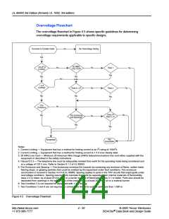
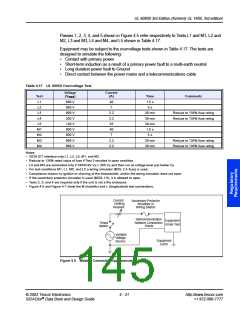
Passes 1, 2, 3, 4, and 5 shown in Figure 4.5 refer respectively to Tests L1 and M1, L2 and
M2, L3 and M3, L4 and M4, and L5 shown in Table 4.17.
Equipment may be subject to the overvoltage tests shown in Table 4.17. The tests are
designed to simulate the following:
•
•
•
•
Contact with primary power
Short-term induction as a result of a primary power fault to a multi-earth neutral
Long duration power fault to Ground
Direct contact between the power mains and a telecommunications cable
Table 4.17 UL 60950 Overvoltage Test
Voltage
Current
(A)
40
7
2.2
2.2
25
40
7
Test
L1
(VRMS
)
Time
1.5 s
5 s
30 min
30 min
30 min
1.5 s
5 s
30 min
30 min
Comments
600 V
600 V
600 V
200 V
120 V
600 V
600 V
600 V
600 V
L2
L3
L4
L5
M1
M2
M3
M4
Reduce to 135% fuse rating
Reduce to 135% fuse rating
2.2
2.2
Reduce to 135% fuse rating
Reduce to 135% fuse rating
Notes:
•
•
•
•
•
•
•
•
ISDN S/T interface only L1, L2, L5, M1, and M2.
Reduce to 135% rated value of fuse if Test 3 resulted in open condition.
L4 and M4 are conducted only if SIDACtor VS O 285 VS and then run at voltage level just below VS.
For test conditions M1, L1, M5, and L5 a wiring simulator (MDL 2 A fuse) is used.
Compliance means no ignition or charring of the cheesecloth, and/or the wiring simulator does not open.
If the secondary protector simulator is used (MDQ 1.6), it is allowed to open.
Tests 2, 3, and 4 are required only if the unit is not a fire enclosure.
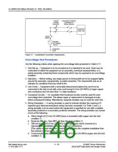
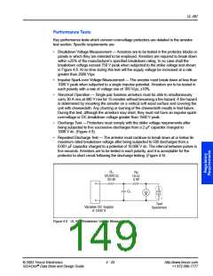
Figure 4.6 and Figure 4.7 show the M (metallic) and L (longitudinal) test connections.
Current
Limiting
Resistor
Secondary Protector
Simulator or
Wiring Station
Telecommunication
Network Connection
Points
Equipment
Under Test
Timed
Switch
Variable
Voltage
Source
Equipment
Earth
Figure 4.6 Metallic Connection Appearances
© 2002 Teccor Electronics
4 - 21
http://www.teccor.com
+1 972-580-7777
®
SIDACtor Data Book and Design Guide

 TECCOR [ TECCOR ELECTRONICS ]