UL 60950 3rd Edition (formerly UL 1950, 3rd edition)
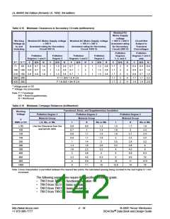
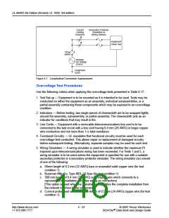
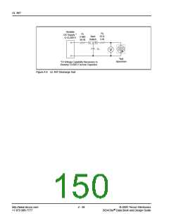
Current
Limiting
Resistors
Secondary Protector
Simulators or
Wiring Stations
Equipment
Under Test
Timed
Switch
Variable
AC Voltage
Source
Equipment
Earth
Figure 4.7 Longitudinal Connection Appearances
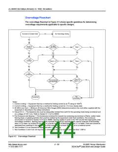
Overvoltage Test Procedures
Use the following criteria when applying the overvoltage tests presented in Table 4.17:
1. Test Set-up — Equipment is to be mounted as it is intended to be used. Tests may be
conducted on either the equipment as an assembly, individual subassemblies, or a
partial assembly containing those components which may be exposed to an overvoltage
condition.
2. Indicators — Before testing, two single pieces of cheesecloth are to be wrapped tightly
around the assembly, subassembly, or partial assembly. The cheesecloth acts as an
indicator for conditions that may result in fire.
3. Line Cords — Equipment with a removable telecommunications line cord is to be
connected to the test circuit with a line cord having 0.4 mm (26 AWG) or larger copper
wire conductors and not more than 1 ꢂ total resistance.
4. Functional Circuitry — UL mandates that functional circuitry must be used for each
overvoltage test conducted. This allows repair or replacement of damaged circuitry
before subsequent testing. Alternatively, separate samples may be used for each test.
5. Wiring Simulators — A wiring simulator is used to indicate whether the maximum I2t
imposed upon telecommunications wiring has been exceeded. For Tests 1 and 5, a
wiring simulator is to be used unless the equipment is specified for use with a suitable
secondary protector or a secondary protector simulator. The wiring simulator can consist
of one of the following:
a. 50mm length of 0.2 mm (32 AWG) bare or enameled solid copper wire (for test
condition 1)
b. Bussman Mfg. Co. Type MDL-2A fuse (for test condition 1)
c. 300 mm length of 0.4 mm (26 AWG) solid copper wire which connects to a
representative installation (includes wiring an connectors)
[This option is used when the manufacturer specifies the complete installation from
the network interface to the equipment.]
d. Current probe used with a 300 mm length of 0.5 mm (24 AWG) copper wire (for test
condition 1)
http://www.teccor.com
+1 972-580-7777
4 - 22
© 2002 Teccor Electronics
SIDACtor Data Book and Design Guide
®

 TECCOR [ TECCOR ELECTRONICS ]