UL 497A
Performance Tests
The following key performance tests relate to overvoltage protection of the secondary
protectors:
1. Impulse Voltage Measurement Test — Secondary protectors must break down within
±25% of the manufacturer’s breakdown rating when tested in each polarity with a rate of
voltage rise of 100 V/µs, ±10%. Note that the manufacturer may assign separate
breakdown voltage ratings for the Breakdown Voltage Measurement Test. This
requirement only applies to secondary protectors that connect between Tip and Ring of
the telephone loop.
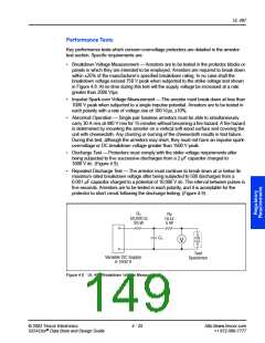
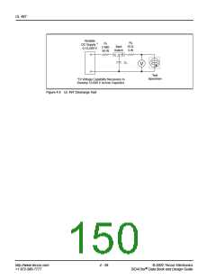
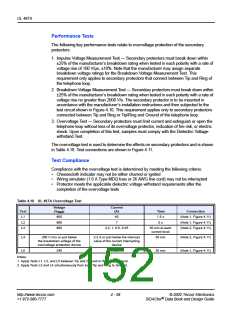
2. Breakdown Voltage Measurement Test — Secondary protectors must break down within
±25% of the manufacturer’s breakdown rating when tested in each polarity with a rate of
voltage rise no greater than 2000 V/s. The secondary protector is to be mounted in
accordance with the manufacturer’s installation instructions and then subjected to the
test circuit shown in Figure 4.10. This requirement applies only to secondary protectors
connected between Tip and Ring or Tip/Ring and Ground of the telephone loop.
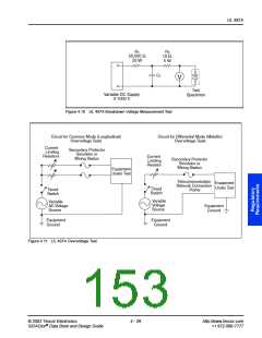
3. Overvoltage Test — Secondary protectors must limit current and extinguish or open the
telephone loop without loss of its overvoltage protector, indication of fire risk, or electric
shock. Upon completion of this test, samples must comply with the Dielectric Voltage-
withstand Test.
The overvoltage test is used to determine the effects on secondary protectors and is shown
in Table 4.18. Test connections are shown in Figure 4.11.
Test Compliance
Compliance with the overvoltage test is determined by meeting the following criteria:
•
•
•
Cheesecloth indicator may not be either charred or ignited
Wiring simulator (1.6 A Type MDQ fuse or 26 AWG line cord) may not be interrupted
Protector meets the applicable dielectric voltage withstand requirements after the
completion of the overvoltage tests
Table 4.18 UL 497A Overvoltage Test
Voltage
Current
(A)
40
Test
L1
(VRMS
)
Time
1.5 s
5 s
Connection
600
(Note 1, Figure 4.11)
(Note 1, Figure 4.11)
(Note 2, Figure 4.11)
L2
600
7
L3
600
2.2, 1, 0.5, 0.25
30 min at each
current level
L4
200 V rms or just below
the breakdown voltage of the
overvoltage protection device
2.2 A or just below the interrupt
value of the current interrupting
device
30 min
30 min
(Note 2, Figure 4.11)
(Note 1, Figure 4.11)
L5
240
24
Notes:
1. Apply Tests L1, L2, and L5 between Tip and Ground or Ring and Ground.
2. Apply Tests L3 and L4 simultaneously from both Tip and Ring to Ground.
http://www.teccor.com
+1 972-580-7777
4 - 28
© 2002 Teccor Electronics
SIDACtor Data Book and Design Guide
®

 TECCOR [ TECCOR ELECTRONICS ]